
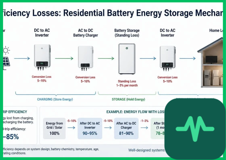
Inverter Conversion Losses and DC-to-AC Power Transformation
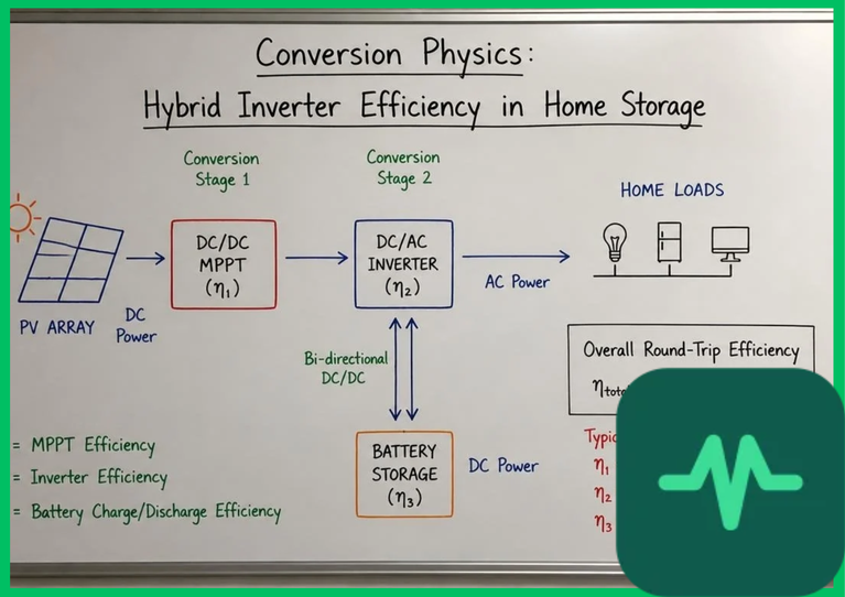
The foundational electrical efficiency barrier in residential energy storage systems stems from power conversion electronics required to bridge direct current (DC) battery storage with alternating current (AC) household loads and municipal grids. Residential energy storage systems utilize bidirectional hybrid inverters or battery-coupled inverters to execute multi-stage power conversion.
During the charging phase, alternating current from residential solar photovoltaic arrays or grid connections ( to
 AC) is rectified into regulated DC voltage (
 to
 DC) via active power factor correction (PFC) stages. During discharging, stored DC battery voltage is inverted back into a synchronized
 or
 AC waveform. Each conversion stage introduces semiconductor switching losses and magnetic core hysteresis losses within internal high-frequency transformers.
Modern residential inverters utilize wide-bandgap silicon carbide (SiC) or gallium nitride (GaN) semiconductor switches, achieving peak conversion efficiencies of 95% to 97%. However, when operating under partial residential load conditions—such as low nighttime baseline loads ( to
 )—inverter efficiency drops precipitously down to 75% to 85%, significantly magnifying conversion losses during extended low-power discharge intervals.
Standby Parasitic Power and Auxiliary System Loads
Beyond active conversion losses, residential battery energy storage systems consume continuous baseline parasitic power to maintain operational readiness, network connectivity, and safety monitoring. When a residential storage inverter sits in idle standby mode—awaiting a grid outage or demand response signal—internal auxiliary systems continue drawing electrical power from the battery pack.
Parasitic auxiliary loads comprise several primary energy sinks:
- BMS and Microcontroller Processing: Battery management system (BMS) microcontrollers, cell-balancing circuits, and communication gateways operate continuously, monitoring individual cell voltages, state of charge (SoC), and temperature telemetry.
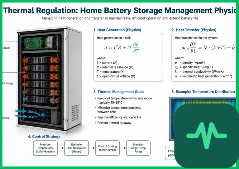
- Thermal Management Actuators: Active liquid cooling pumps, heating elements, and enclosure ventilation fans consume auxiliary power to keep battery cell cores within optimal thermal thresholds (
 to
 [
 to
 ]).
- Inverter Control Circuitry: Power supply units and display interfaces maintain active standby status, drawing a baseline parasitic load ranging from
 to
 continuously.
Over an annual operating cycle, continuous standby parasitic consumption can waste  to
 of stored electricity, degrading overall system round-trip efficiency, particularly in households with low daily throughput.
Technical Data Specifications of Residential Battery Storage Parameters
| Residential Storage Efficiency Parameter | Engineering Specification Standard |
|---|---|
| System Round-Trip Efficiency (RTE) | 80% to 90% AC-to-AC residential efficiency |
| Bidirectional Inverter Peak Efficiency | 95% to 97% using Silicon Carbide (SiC) switches |
Inverter Efficiency at Low Partial Load ( ) | 75% to 85% reduced conversion efficiency |
| Standby Parasitic Power Consumption |  to  continuous idle draw |
| Battery Cell Chemistry | Lithium Iron Phosphate ( [LFP]) |
| Recommended Depth of Discharge (DoD) | 80% to 90% operational limit for longevity |
Internal DC Resistance ( ) |  per module string |
Electrochemical Resistance and Internal Joule Heating
Internal electrochemical losses within residential battery packs are governed by internal direct current resistance ( ) and overpotential voltage drops during high-rate charging and discharging. When current (
 ) flows through the lithium-ion cell matrix, internal resistance generates thermal energy via Joule's law (
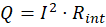 ), causing overpotentials that reduce output discharge voltage relative to open-circuit voltage (
 ).
Residential storage systems predominantly utilize lithium iron phosphate ( [LFP]) chemistry due to superior safety profiles and high cycle durability. However, LFP cells exhibit lower ionic conductivity and higher polarization resistance compared to nickel-manganese-cobalt (NMC) alternatives, resulting in slightly higher internal resistance voltage drops under high-rate household power draws (such as operating electric vehicle chargers or heat pumps simultaneously). These internal overpotentials dissipate active energy as core thermal heat, requiring active or passive thermal management systems to stabilize cell temperatures.
Depth of Discharge (DoD) Optimization and Capacity Fade
Optimizing residential storage efficiency requires balancing usable capacity against depth of discharge (DoD) thresholds. Discharging a residential battery pack to 100% DoD accelerates chemical degradation, induces mechanical stress within graphite anodes and LFP crystal lattices, and shortens nominal cycle life.
Residential inverter control algorithms enforce conservative DoD limits (typically 80% to 90%), reserving an unallocated state-of-charge buffer to prevent deep discharge voltage collapse and protect auxiliary reserve capacity for emergency grid outages. Managing DoD and operating within strict temperature parameters minimizes capacity fade, ensuring that residential battery storage systems maintain high round-trip efficiency across their 10- to 15-year operational lifespans.
The Final Take
Mastering residential battery energy storage round-trip efficiency requires rigorous control over bidirectional inverter conversion losses, standby parasitic power consumption, and internal electrochemical resistance. Citing IEA distributed energy assessments, minimizing partial-load conversion penalties and optimizing thermal management preserves system efficiency between 80% and 90%. By addressing these thermodynamic and power electronic loss mechanisms, residential energy storage systems deliver reliable, high-efficiency performance for decentralized clean energy consumers.
Comments (0)
Login to leave a comment.
No comments yet. Be the first to share your thoughts!