
Electrochemical Kinetics and Nernst Potential Equations
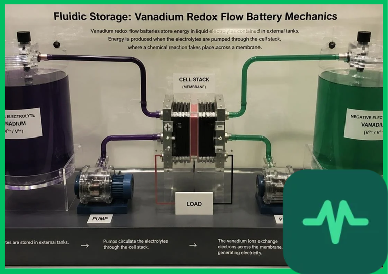
The foundational electrochemistry governing vanadium redox flow batteries relies on four distinct vanadium oxidation states dissolved in aqueous sulfuric or hydrochloric acid supporting electrolytes. The negative half-cell reaction cycles reversibly between divalent and trivalent vanadium ions ( ), while the positive half-cell reaction cycles between oxovanadium(IV) and dioxovanadium(V) ions (
 ).
The theoretical open-circuit voltage ( ) of the vanadium redox cell is formulated mathematically by the Nernst equation:

where  is standard cell potential (
 ),
 is the universal gas constant,
 is absolute temperature (
 ),
 is the Faraday constant, and bracketed terms represent chemical species concentrations within the circulating liquid electrolytes.
During charging, electrical energy forces electrons from the positive electrode to the negative electrode, oxidizing  to
 at the positive half-cell and reducing
 to
 at the negative half-cell. Discharging reverses this electrochemical pathway, releasing electrical energy back to the power grid.
Membrane Permeability Mechanics and Ion Crossover Mitigation
A primary technical challenge constraining vanadium redox flow battery operational efficiency is ion crossover across the ion-exchange membrane separating the positive and negative half-cells. Perfluorosulfonic acid (PFSA) membranes—such as standard Nafion polymer films—allow proton ( ) migration to maintain electrical charge neutrality during operation while attempting to block vanadium ion transport.
However, imperfect membrane selectivity permits slow diffusion of vanadium ions ( ,
 ,
 ,
 ) across the polymer matrix down concentration gradients. Vanadium ion crossover induces capacity self-discharge and chemical imbalances between the two half-cell electrolyte reservoirs, gradually degrading total energy storage capacity over multi-cycle operational intervals.
To counteract ion crossover, modern VRFB systems deploy advanced composite membranes, sulfonated aromatic polymers, or sub-nanometer porous ceramic separators. These engineered membranes suppress vanadium ion permeability by an order of magnitude compared to legacy separators while preserving high proton conductivity and minimizing cell ohmic resistance.
Technical Data Specifications of Vanadium Redox Flow Batteries
| Vanadium Flow Battery Parameter | Engineering & Electrochemical Specification Standard |
|---|---|
| System Round-Trip Efficiency (RTE) | 75% to 85% net operational efficiency |
| Electrolyte Operating Temperature Range |  to  (  to  ) |
| Capacity Degradation Rate |  per equivalent full cycle via rebalancing |
| Membrane Permeability Standard | Perfluorosulfonic acid (PFSA) or sulfonated polymers |
| Stack Power Density Output |  to  active electrode area |
| Discharge Duration Capacity | 4 to 12+ hours continuous rated power delivery |
| Electrolyte Supporting Acid Concentration | Aqueous  sulfuric acid (  ) |
Electrolyte Degradation Kinetics and Thermal Management
Operating vanadium redox flow batteries requires strict thermal management to prevent detrimental electrolyte degradation kinetics. Vanadium species solubility within aqueous acid solutions is highly temperature-dependent.
When operating electrolyte temperatures exceed  (
 ), pentavalent vanadium ions (
 ) undergo irreversible thermal precipitation, forming insoluble vanadium pentoxide (
 ) crystal sludge. This solid precipitate clogs porous carbon felt electrodes, increases hydraulic pressure drops, and permanently alters active vanadium concentration ratios. Conversely, electrolyte temperatures dropping below
 (
 ) cause divalent vanadium salts to crystallize out of solution.
Consequently, industrial VRFB installations incorporate active thermal management systems, including titanium plate heat exchangers and closed-loop liquid cooling pumps, maintaining electrolyte temperatures within strict operational boundaries. Furthermore, chemical stabilizing additives—such as hydrochloric acid co-solvents or phosphoric acid compounds—are blended into the supporting electrolyte to suppress  precipitation and elevate maximum electrolyte energy density limits.
Round-Trip Efficiency and Hydraulic Pump Parasitic Losses
Evaluating overall vanadium redox flow battery performance requires analyzing round-trip efficiency (RTE), which represents the ratio of electrical energy discharged to electrical energy input during charging:

Coulombic efficiency ( ) exceeds 95% to 98% in optimized systems, limited primarily by minor side reactions (such as hydrogen evolution at the negative electrode) and cross-contamination. Voltage efficiency (
 ) ranges from 80% to 88%, constrained by ohmic resistance across carbon felt electrodes, bipolar graphite plates, and current collectors, as well as electrochemical activation overpotentials.
Additionally, hydraulic pumping parasitic losses consume 3% to 7% of total generated system power. Pumping energy must overcome viscous fluid drag and pressure drops across external plumbing manifolds and porous electrode flow fields. Optimizing variable-speed hydraulic pump flow rates relative to real-time current density minimizes parasitic energy consumption, maximizing net system round-trip efficiency.


Comments (0)
Login to leave a comment.
No comments yet. Be the first to share your thoughts!