
Thermodynamic Foundations of Compression and Expansion Mechanics
The operational efficiency of compressed air energy storage is dictated by the thermodynamic behavior of gases undergoing large pressure variations. During the charging phase, electrical energy drives industrial multi-stage compressors that elevate atmospheric air pressure up to  to
 (
 ). This pneumatic compression process follows polytropic thermodynamic principles, where work input is converted directly into internal thermal energy and pressure elevation.
The temperature ( ) of the compressed gas exiting a polytropic compression stage is quantified by the relation:
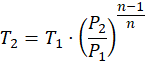
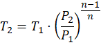
where  represents initial ambient temperature,
 and
 denote initial and final pressures, and
 is the polytropic exponent. Without thermal management, compressing ambient air to high operating pressures generates extreme air temperatures exceeding
 to
 (
 to
 ).
In traditional diabatic systems, releasing this thermal energy into the atmosphere wastes up to 50% of the initial electrical input energy. Advanced adiabatic CAES architectures capture this thermal energy across multi-stage shell-and-tube or packed-bed heat exchangers, storing the heat within solid media (such as ceramic bricks, cast basalt, or phase-change materials) before routing the cooled, high-pressure air into underground storage containment caverns.
Underground Cavern Pressure Containment and Geological Engineering
The physical storage vessel in utility-scale compressed air energy storage is a geological formation or engineered containment structure capable of withstanding immense pneumatic pressures. Suitable geological sites include solution-mined salt caverns, deep porous rock formations, depleted hydrocarbon reservoirs, and lined hard-rock underground caverns.
Salt caverns provide superior mechanical stability and zero permeability due to the viscoplastic creep properties of rock salt, which self-heals micro-fissures under high lithostatic pressure. Maintaining structural integrity within underground salt caverns requires strict pressure boundary limits:
- Minimum Operational Pressure: Cavern pressure must remain above
 (
 ) to prevent structural roof collapse, cavern wall spalling, or cavity convergence.
- Maximum Operational Pressure: Pressure must not exceed lithostatic stress thresholds (typically
 to
 [
 ]) to avoid hydraulic fracturing of the surrounding salt strata.
- Mass Flow Rate Regulation: Injection and extraction flow rates must balance pneumatic pressure differentials, preventing sudden thermodynamic shocks or temperature drops that induce thermal stress on wellbore casing strings.
Thermal Heat Exchanger Efficiency and Packed-Bed Storage
The core technological differentiator of adiabatic CAES systems is the thermal heat exchanger efficiency linking the compression train to the thermal energy storage (TES) reservoir. During the charging cycle, high-temperature compressed air passes through recuperative heat exchangers, transferring thermal energy to solid storage media with thermal recovery efficiencies exceeding 90%.
During the discharge phase, high-pressure air extracted from the underground cavern flows in reverse through the thermal storage bed, absorbing stored heat and re-heating the air to temperatures between  and
 (
 to
 ) prior to expansion through high-pressure and low-pressure pneumatic turbines. Packed-bed thermal storage systems utilize high-density ceramic spheres or alumina bricks characterized by high volumetric heat capacity and low thermal conductivity, minimizing parasitic thermal losses during multi-day idle storage intervals.
Technical Data Specifications of Compressed Air Energy Storage Parameters
| Thermodynamic & Physical Parameter | Engineering Specification Range |
|---|---|
| Compressor Operating Pressure Range |  to  (  ) |
| Cavern Minimum Containment Pressure |  (  ) structural lower limit |
| Thermal Storage Media Temperature |  to  (  to  ) |
| Thermal Heat Exchanger Efficiency | 90% to 95% thermal energy recovery rate |
| Adiabatic CAES Round-Trip Efficiency | 65% to 75% total electrical energy retention |
| Diabatic CAES Round-Trip Efficiency | 45% to 55% (requiring natural gas co-firing) |
| Discharge Power Capacity Range |  to  (  ) |
Turbine Expansion Physics and Power Generation Optimization
Extracting electrical power from stored compressed air relies on multi-stage expansion turbines coupled directly to synchronous electrical generators. As high-pressure air expands through turbine expansion stages, gas temperature drops sharply in accordance with polytropic expansion equations. Re-heating the air via the thermal energy storage system immediately before each turbine stage prevents moisture condensation, blade frosting, and mechanical cavitation.
Advanced turbine designs incorporate variable-geometry nozzles and radial-inflow expansion geometries optimized to handle fluctuating inlet pressures as cavern air mass depletes during multi-hour discharge cycles. Regulating expansion mass flow rates maintains stable electrical frequency output ( or
 ) across the grid interconnection bus, satisfying stringent power quality standards.
Round-Trip Efficiency Optimization and Economic Viability
Optimizing compressed air energy storage thermodynamic cycles requires balancing capital expenditures against aggregate round-trip efficiency ( ). While traditional diabatic CAES achieves lower round-trip efficiencies (45% to 55%) due to thermal venting and fossil fuel reliance, advanced adiabatic CAES achieves round-trip efficiencies between 65% and 75%.
Levelized cost of storage (LCOS) analyses published by the IEA and academic energy engineering institutions confirm that CAES systems exhibit exceptionally low capital costs per kilowatt-hour ( ) compared to electrochemical batteries when discharge durations exceed 10 to 24 hours. Decoupling power capacity from energy storage capacity allows system operators to scale storage duration simply by expanding underground cavern volume. By mastering pneumatic compression thermodynamics, thermal energy storage recuperation, and geological cavern containment, compressed air energy storage establishes an indispensable technical foundation for long-duration grid decarbonization.

Comments (0)
Login to leave a comment.
No comments yet. Be the first to share your thoughts!