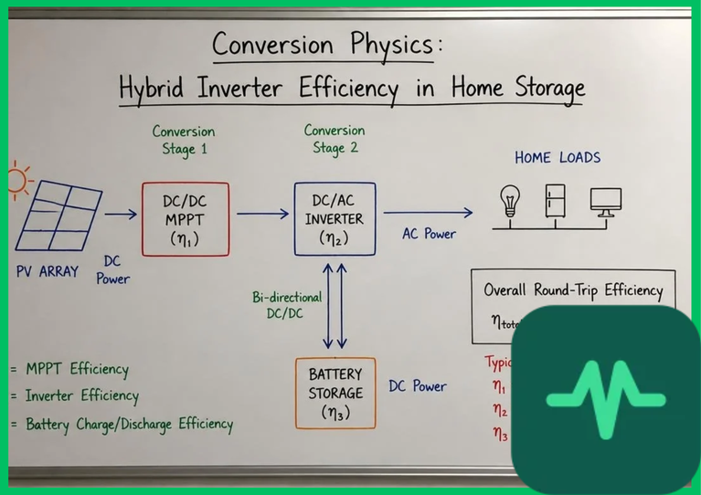
DC-Coupled versus AC-Coupled Hybrid Inverter Architectures
Maximizing round-trip efficiency begins with selecting the appropriate system topology for power flow integration: DC-coupled or AC-coupled. Each architecture imposes distinct conversion steps and thermodynamic loss profiles.
- DC-Coupled Architecture: Photovoltaic strings and battery energy storage systems share a common high-voltage DC bus. Solar energy generated by PV panels passes through a DC-DC boost converter before charging the battery directly or flowing through a central bidirectional DC-AC inverter to supply household loads. This topology features fewer power conversion stages, eliminating double conversion losses when storing solar energy directly into the battery. Round-trip efficiency for DC-coupled systems typically ranges between 90% and 95%.
- AC-Coupled Architecture: Photovoltaic strings connect to a dedicated solar inverter converting DC to AC power. When excess solar energy is available, a secondary battery inverter rectifies this AC power back into DC to charge the battery storage pack, and subsequently inverts it back to AC during discharge. This dual-conversion process incurs compounding energy losses, reducing cumulative round-trip efficiency to between 82% and 88%.
While AC-coupled systems offer greater flexibility for retrofitting energy storage onto existing solar installations, DC-coupled hybrid inverters achieve superior conversion efficiency by minimizing intermediate rectification stages.
Semiconductor Switching Physics and Wide-Bandgap Devices
The conversion efficiency of a hybrid inverter is dictated by the electrical behavior of its semiconductor switches during pulse-width modulation (PWM). Legacy inverters utilize silicon insulated-gate bipolar transistors (IGBTs) that exhibit high switching tail currents and elevated conduction losses at high frequencies ( to
 ).
Modern high-performance hybrid inverters replace silicon IGBTs with wide-bandgap silicon carbide ( ) MOSFETs or gallium nitride (
 ) switches. Silicon carbide material properties include a wide bandgap energy (
 ), a high critical breakdown electric field strength, and high electron saturation velocity. These characteristics reduce energy losses during high-frequency switching operations (
 to
 ):
- Switching Losses (
 ):
 MOSFETs eliminate tail current during turn-off transients, cutting switching energy losses by up to 75% compared to silicon IGBT counterparts.
- Conduction Losses: Low drain-source on-state resistance (
 ) minimizes resistive heating (
 ) during high-current DC-AC and DC-DC power transfer.
- Thermal Dissipation: High thermal conductivity substrates allow efficient heat extraction, maintaining semiconductor junction temperatures below
 (
 ) without requiring bulky forced-air cooling fans.
DC-Link Voltage Regulation and Standby Power Consumption
Maintaining stable DC-link voltage across fluctuating solar irradiance and variable residential load profiles is critical for hybrid inverter performance. The intermediate DC-link capacitor bank acts as an energy buffer, smoothing voltage ripples between the PV array, battery terminals, and the grid-tied inverter stage.
Voltage fluctuations across the DC bus induce ripple currents that accelerate electrolytic capacitor degradation and increase magnetic core losses within high-frequency inductors and transformers. Advanced hybrid inverters utilize multi-level converter topologies (such as neutral-point-clamped circuits) to minimize harmonic distortion and maintain tight DC-link voltage regulation ( ) across wide operating loads.
Furthermore, standby power consumption—the parasitic electrical draw required to maintain inverter control boards, microcontrollers, and communication gateways when no loads are active—represents a significant efficiency penalty during low-utilization periods. High-efficiency hybrid inverters minimize idle parasitic losses to less than  to
 , preserving stored battery capacity during extended standby intervals.
Technical Data Specifications of Hybrid Inverter Parameters
| Electrical & Thermal Parameter | Engineering Specification Range |
|---|---|
| Peak Round-Trip Efficiency (DC-Coupled) | 92.0% to 96.5% total energy retention |
| Peak Round-Trip Efficiency (AC-Coupled) | 85.0% to 89.5% total energy retention |
| DC Bus Operating Voltage Range |  to  DC high-voltage bus |
| Inverter PWM Switching Frequency |  to  operational range |
| Standby Idle Power Consumption |  to  parasitic electrical draw |
| Semiconductor Switch Technology | Wide-bandgap Silicon Carbide ( ) MOSFET |
| Maximum Continuous Power Output |  to  residential capacity |
Thermal Management and Enclosure Cooling Mechanics
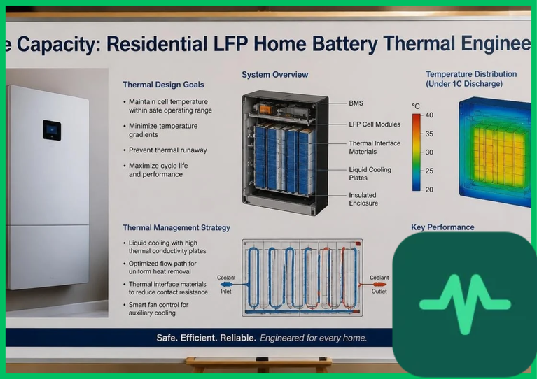
Power conversion inefficiencies manifest directly as thermal energy waste within the hybrid inverter enclosure. Internal semiconductor junction heating, magnetic core losses in transformers, and copper winding resistance generate concentrated thermal loads. Unmanaged heat accelerates electronic component degradation and triggers thermal derating protocols, restricting power output during peak summer intervals.
Engineering robust thermal management requires replacing noisy, failure-prone mechanical cooling fans with extruded aluminum passive heat sinks or closed-loop liquid-cooled cold plates. Convection cooling fins are optimized via computational fluid dynamics (CFD) to maximize natural heat dissipation across ambient operating temperatures ranging from  to
 (
 to
 ). Maintaining optimal operating temperatures prevents thermal runaway of internal capacitors and ensures consistent conversion efficiency across diverse global climates.
Grid-Tied Synchronization and Power Quality Metrics
Hybrid inverters perform a dual operational role: managing internal battery storage and synchronizing power delivery with the local utility distribution grid. During grid-tied operation, the inverter outputs a synchronized three-phase or single-phase sinusoidal AC waveform matching grid frequency ( or
 ) and phase angle.
In compliance with international grid interconnection standards (such as IEEE 1547 and IEC 61850), hybrid inverters must maintain strict power quality metrics:
- Total Harmonic Distortion (THD): Injected AC current must maintain a THD below 3.0% to prevent grid transformer overheating and voltage distortion.
- Power Factor Control: Inverters dynamically adjust reactive power (
 ) independently of active power (
 ), providing voltage support during local grid disturbances.
- Anti-Islanding Protection: Rapid islanding detection algorithms disconnect the inverter from the grid within
 during blackouts, preventing back-feeding hazards for utility line repair crews.
The Final Take
Optimizing hybrid inverter round-trip efficiency requires rigorous engineering control over semiconductor switching physics, DC-coupled topologies, thermal management, and power quality synchronization. Citing ENERGY STAR residential performance data and IEA energy storage research, deploying wide-bandgap silicon carbide semiconductors and advanced DC-coupled architectures minimizes conversion losses, maximizing the economic and environmental value of residential energy storage systems.



Comments (0)
Login to leave a comment.
No comments yet. Be the first to share your thoughts!