 (
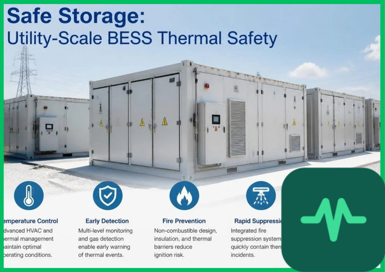
 ). Mitigating these risks requires rigorous engineering integration of early-stage lithium-ion off-gas detection, advanced thermal propagation barriers, robust fire suppression fluid dynamics, and strict international safety standards.
Exothermic Decomposition Kinetics and Thermal Runaway Stages
Thermal runaway in lithium-ion battery cells is a sequential, self-accelerating exothermic chain reaction driven by internal chemical degradation. The degradation cascade typically initiates when localized cell temperatures rise above  to
 (
 to
 ) due to internal resistive heating or external thermal abuse:
- SEI Decomposition: The protective solid-electrolyte interphase (SEI) layer on the graphite anode decomposes at temperatures between
 and
 (
 to
 ), exposing reactive carbon surfaces to the liquid carbonate electrolyte.
- Anode-Electrolyte Exothermic Reactions: Exposed lithium-carbon complexes react exothermically with organic solvents, generating hydrocarbon gases and initiating self-heating rates exceeding
 (
 ).
- Separator Melting: As temperatures approach
 to
 (
 to
 ), the polyolefin separator (polyethylene or polypropylene) melts and shrinks, causing direct physical contact between the cathode and anode, triggering massive internal short-circuit currents.
- Cathode Decomposition and Oxygen Release: At temperatures surpassing
 (
 ), transition metal oxide cathodes undergo thermal decomposition, releasing structural oxygen that reacts violently with organic solvents and drives internal cell pressures above
 (
 ), rupturing the cell casing and initiating full thermal runaway.
Lithium-Ion Off-Gas Detection and Early Warning Physics
Detecting thermal runaway prior to actual thermal ignition is critical for utility-scale battery energy storage system (BESS) safety. When a cell enters the initial venting phase—long before visible flames or high temperatures register on traditional thermocouples—it expels a complex mixture of off-gases. This off-gas signature comprises hydrogen ( ), carbon monoxide (
 ), carbon dioxide (
 ), and volatile organic compounds (VOCs) such as ethylene carbonate and dimethyl carbonate.
Advanced BESS safety architectures deploy specialized off-gas sensors positioned within battery enclosure exhaust plenums and module racks. These multi-parameter detectors measure changes in ambient gas concentration, aerosol density, and pressure fluctuations with response times under 5 seconds. Detecting parts-per-million ( ) concentration spikes of hydrogen or carbon monoxide enables the battery management system (BMS) to isolate the affected rack, trip electrical contactors, and activate containment ventilation before cell-to-cell thermal propagation occurs.
Thermal Propagation Barriers and Module Isolation
Preventing a single failing cell from propagating thermal runaway to adjacent cells within a module requires robust thermal propagation barriers. Without physical isolation, the intense radiant heat flux and direct flame impingement of a runaway cell ( [
 ]) will successively ignite neighboring cells through direct conduction and convection.
Engineering effective thermal barriers involves placing high-performance insulation materials between individual prismatic or pouch cells:
- Silica Aerogel Blankets: Integrating ultra-thin (
 to
 [
 ]) hydrophobic silica aerogel sheets restricts conductive heat transfer due to their ultra-low thermal conductivity (
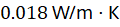 ).
- Mica and Ceramic Composite Plates: Placing rigid mica sheets or intumescent ceramic coatings between module partitions expands when exposed to heat, sealing gaps and blocking direct flame paths.
- Liquid Cooling Plate Isolation: Designing aluminum liquid-cooled cold plates with internal burst channels ensures that cooling fluid absorbs and rejects localized heat surges during initial cell venting events.
Technical Data Specifications of BESS Safety Parameters
| BESS Safety & Thermal Parameter | Engineering Specification Range |
|---|---|
| Thermal Runaway Trigger Temperature |  to  (  to  ) |
| Radiant Runaway Flame Temperature |  to  (  to  ) |
| Off-Gas Sensor Response Time | 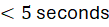 for  and  detection |
| Aerogel Blanket Thermal Conductivity | 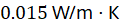 to 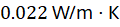 |
| Container Deflagration Venting Pressure |  to  ( 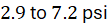 ) |
| Clean Agent Discharge Concentration | 6% to 9% by volume for total flooding |
| UL 9540A Propagation Test Limit | Zero thermal propagation outside tested module |
Fire Suppression Fluid Dynamics and Deflagration Mitigation
When thermal runaway breaches module containment and releases large quantities of flammable gases into a closed utility-scale battery enclosure, active fire suppression fluid dynamics become paramount. Accumulating hydrogen and hydrocarbon vapors inside a sealed container create an explosive atmosphere susceptible to deflagration if an ignition source meets stoichiometric mixing ratios.
Modern BESS installations integrate multi-stage fire suppression systems combining clean gaseous agents (such as FK-5-1-12 or HFC-227ea) with water mist suppression loops. Clean agents flood the enclosure volume within 10 seconds of sensor activation, starving gas-phase combustion and interrupting radical chain reactions. However, because internal battery pack fires are driven by self-sustaining exothermic chemical reactions within sealed cell casings, gaseous agents alone cannot cool the deep core temperature of the battery cells.
Consequently, secondary water mist or sprinkler systems discharge high-pressure water droplets ( to
 droplet size) to provide latent heat vaporization cooling, dropping core module temperatures below the critical
 threshold. To prevent structural over-pressurization during explosive off-gas venting, container housings incorporate calibrated explosion-relief blowout panels designed to rupture at low internal pressures (
 to
 ), venting gases safely away from personnel access zones.
International Safety Standards and Regulatory Compliance
Deploying utility-scale energy storage systems globally requires strict compliance with international fire safety standards and rigorous testing protocols. Standards such as NFPA 855 (Standard for the Installation of Stationary Energy Storage Systems) and UL 9540A (Test Method for Evaluating Thermal Runaway Fire Propagation in Battery Energy Storage Systems) establish mandatory engineering benchmarks.
The UL 9540A test protocol requires full-scale physical testing of a representative battery rack to determine whether a single-cell thermal runaway event will propagate to adjacent cells, modules, and units. Quantitative safety evaluations published by academic research consortia and the IEA confirm that adhering to NFPA 855 separation distances, deflagration venting calculations, and UL 9540A containment validations successfully eliminates catastrophic fire risks. By integrating off-gas sensors, aerogel barriers, and multi-stage suppression fluid dynamics, utility-scale BESS installations achieve robust thermal safety across global electrical grid networks.




Comments (0)
Login to leave a comment.
No comments yet. Be the first to share your thoughts!