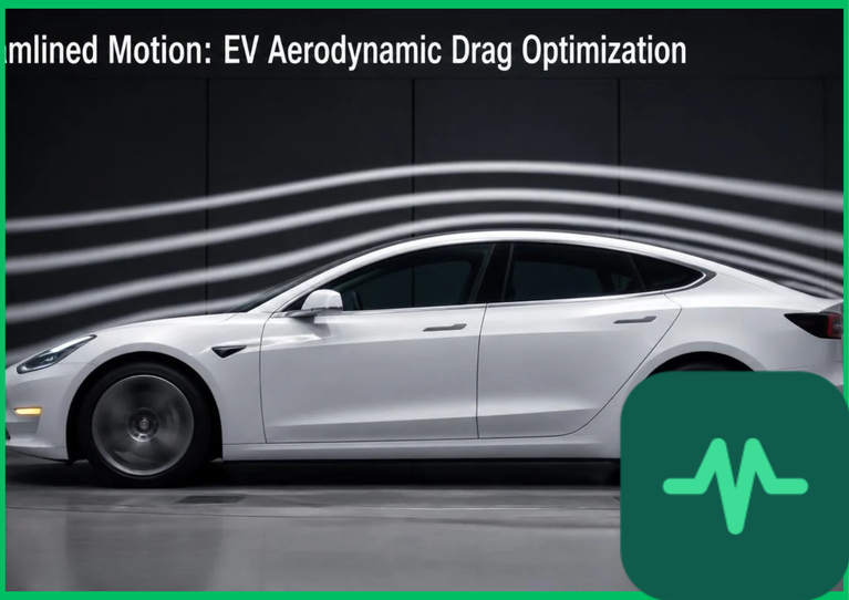
 (
 ). Unlike internal combustion engine vehicles that waste significant thermal energy via exhaust and cooling systems—reducing the relative penalty of aerodynamic drag—electric vehicles possess high powertrain conversion efficiencies exceeding 90%. Consequently, overcoming aerodynamic drag consumes up to 50% of total battery energy output during highway cruising. Achieving extended operational range requires rigorous engineering control over drag coefficients (
 ), frontal surface areas (
 ), underbody airflow smoothing, active cooling management, and computational fluid dynamics (CFD) optimization.
Aerodynamic Physics and the Drag Equation
The fundamental physical relationship governing aerodynamic resistance is the aerodynamic drag force equation ( ):
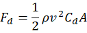
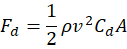
where  represents air density (
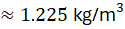 at sea level [
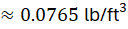 ]),
 is vehicle velocity relative to the air stream,
 is the dimensionless drag coefficient, and
 denotes the vehicle frontal cross-sectional area. Because drag force scales quadratically with velocity (
 ), the mechanical power consumption required to overcome aerodynamic resistance scales cubically:
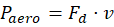
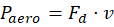
In practical engineering terms, reducing the drag coefficient from  to
 on a vehicle with a frontal area of
 (
 ) traveling at
 (
 ) yields a reduction in aerodynamic drag force exceeding 26%. This reduction translates directly into an increased driving range of 40 to 60 kilometers (
 to
 miles) per battery charge cycle without increasing battery storage capacity or total vehicle mass.
Underbody Airflow Smoothing and Diffuser Integration
Traditional automotive undercarriages feature exposed suspension components, exhaust pipes, transmission tunnels, and structural crossmembers that generate severe turbulent boundary layer separation and high-pressure form drag. Electric vehicle platforms offer structural advantages for aerodynamic optimization because flat battery packs integrated into the floorpan create a naturally smooth lower boundary.
Maximizing underbody aerodynamic efficiency requires sealing the entire lower floorpan with composite or aluminum undertray panels. These smooth panels accelerate underbody airflow velocity, lowering static pressure beneath the vehicle in accordance with Bernoulli's principle. To manage the high-velocity air exiting the rear underbody, automotive engineers integrate curved rear diffusers. These diffusers expand the flow cross-section gradually, decelerating the air smoothly and re-attaching it to the ambient wake without generating high-pressure turbulent wake zones or parasitic lift forces.
Active Grille Shutters and Cooling Airflow Management
Balancing aerodynamic drag reduction with powertrain thermal management presents a persistent engineering compromise. Internal powertrain components—such as the permanent-magnet traction motor, high-frequency silicon carbide inverter, and lithium-ion battery pack—require continuous cooling airflow through front grille openings to maintain safe operating temperatures. However, open grilles allow high-pressure air to enter the engine bay, creating internal turbulence and increasing overall drag by 10% to 15%.
Electric vehicles resolve this thermodynamic conflict by integrating active grille shutters (AGSs). Controlled by the vehicle management system based on real-time thermistor telemetry, AGS actuators modulate louver positions dynamically:
- Closed Position: During high-speed highway cruising when thermal loads are moderate, shutters close completely, forcing stagnation air to flow smoothly around the exterior body contour rather than entering the turbulent engine bay cavity.
- Open Position: During low-speed urban driving, heavy regenerative braking, or high-discharge acceleration events, shutters open fully to maximize convective cooling air mass flow across heat exchangers.
Computational Fluid Dynamics (CFD) and Wind Tunnel Validation
Designing low-drag vehicle geometries requires iterative multi-phase computational fluid dynamics (CFD) simulations running Navier-Stokes equations and turbulence closure models (such as  Shear Stress Transport [SST] models) on high-performance computing clusters. CFD software models air molecule interactions across millions of computational grid cells, identifying localized vortex formation, pressure gradients, and boundary layer separation zones.
Following digital optimization, physical scale models ( to full-scale) undergo rigorous wind tunnel testing equipped with moving ground planes and rolling-road balance dynamometers to simulate real-world road friction and wheel rotation dynamics. Smoke visualization and surface oil-flow testing validate CFD models, ensuring production vehicle designs achieve target drag coefficients below
 .
Technical Data Specifications of Aerodynamic Parameters
| Aerodynamic & Physical Parameter | Engineering Specification Range |
|---|---|
Target Drag Coefficient ( ) |  to  for modern high-efficiency EVs |
Vehicle Frontal Area ( ) |  to  ( 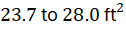 ) |
Air Density ( at Sea Level) | 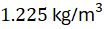 ( 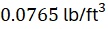 ) |
| CFD Turbulence Modeling |  SST Navier-Stokes simulation |
| Active Grille Shutter Response Time | 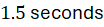 to  full actuation |
| Underbody Floorpan Coverage | 85% to 98% flat composite panel enclosure |
| High-Speed Range Extension Yield | 8% to 15% increased highway driving distance |
Wheel and Cavity Aerodynamics
Wheel assemblies and wheel-arch cavities account for up to 30% of total vehicle aerodynamic drag due to rotating-wheel turbulence, aerodynamic pumping, and flow separation. As wheels spin, they pump high-velocity air outward, creating disruptive vortices along the vehicle flanks.
Mitigating wheel drag requires closed-face aerodynamic wheel designs utilizing flush composite aero-inserts that minimize open spoke cavities. Furthermore, engineers integrate air curtains—vertical slots carved into the front bumper corners that ingest ambient air and accelerate it outward across the outer face of the front tires. This high-velocity air jet creates an aerodynamic seal that prevents lateral airflow from separating around the wheel arches, smoothing the wake profile along the vehicle body sides.
The Final Take
Optimizing electric vehicle aerodynamics through advanced computational modeling, underbody smoothing, active grille shutters, and wheel-arch air curtains establishes a critical engineering foundation for maximizing highway efficiency. Citing automotive engineering literature and international transport research, minimizing drag coefficients decouples high-speed driving range from battery pack mass expansion, ensuring sustainable, high-efficiency electric mobility.

Comments (0)
Login to leave a comment.
No comments yet. Be the first to share your thoughts!