

 ) degradation when ambient outdoor temperatures drop below
 (
 ). As ambient temperatures decline, suction density drops, mass flow rate through the compressor decreases, and the total pressure ratio surges beyond safe mechanical thresholds. Vapor-injection technology—incorporating either flash tank separators or internal heat exchanger economizers—injects intermediate-pressure refrigerant vapor directly into the compression chamber, stabilizing mass flow and extending operating envelopes down to
 (
 ) without relying on inefficient electrical resistance strip heaters. Analyzing thermodynamic cycle mechanics, scroll compressor enthalpy expansion, and mass flow augmentation is essential for evaluating cold climate heat pump efficiency.
Thermodynamic Limitations of Standard Vapor-Compression Cycles at Low Ambients
The foundational thermodynamic challenge governing cold climate heat pump operation stems from the physical properties of refrigerant mass flow under high compression ratios. In standard single-stage vapor-compression cycles, refrigerant evaporation occurs at low suction pressures corresponding to cold outdoor ambient temperatures. As the outdoor temperature drops from  (
 ) to
 (
 ), the evaporating pressure decreases exponentially, reducing the density of the suction vapor entering the compressor inlet.
Because positive displacement compressors displace a fixed volumetric sweep rate ( ), lower suction vapor density results in a direct reduction in mass flow rate (
 ). Heating capacity (
 ) is directly proportional to mass flow rate multiplied by the specific enthalpy change across the condenser:

When mass flow rate collapses due to low suction density, total heating capacity drops by 40% to 60%. Furthermore, the system pressure ratio ( ) escalates from nominal operating ratios of
 up to
 or higher. High pressure ratios elevate discharge gas temperatures excessively, degrading compressor lubricating oils, threatening scroll wrap structural integrity, and reducing volumetric efficiency due to re-expansion losses in compressor clearance volumes.
Flash Tank Vapor Injection and Economizer Circuitry
To counteract capacity collapse at sub-zero temperatures, advanced cold climate heat pumps integrate vapor-injection architectures utilizing either a flash tank separator (FTS) or a brazed-plate internal heat exchanger (IHX) economizer.
In a flash tank vapor injection system, liquid refrigerant exiting the condenser is expanded through a primary electronic expansion valve (EEV-1) into a vertical flash tank vessel maintained at an intermediate saturation pressure ( ). Inside the flash tank, the refrigerant separates into saturated liquid at the bottom and saturated vapor at the top. The saturated liquid passes through a secondary expansion valve (EEV-2) into the main outdoor evaporator coil, where it absorbs heat from sub-zero ambient air.
Simultaneously, the saturated intermediate-pressure vapor from the top of the flash tank is routed directly through an injection port into the mid-stage compression pockets of a specialized scroll compressor. This dual-stream routing bypasses the evaporator for a fraction of the mass flow, increasing total refrigerant mass circulation through the condenser without over-burdening the low-stage suction inlet.
Technical Data Specifications of Cold Climate Vapor-Injection Systems
| Vapor-Injection System Parameter | Engineering & Thermodynamic Specification Standard |
|---|---|
| Minimum Operating Ambient Temperature |  to  (  to  ) |
| Intermediate Injection Pressure Ratio |  optimal geometric mean |
Heating Capacity Boost at  (  ) | 25% to 40% capacity augmentation vs. baseline |
Coefficient of Performance ( ) Gain | 15% to 30% improvement at low ambient conditions |
| Compressor Discharge Temperature Control | Suppressed by  to  (  to  ) via desuperheating |
| Refrigerant Mass Flow Amplification | 20% to 35% higher condenser mass circulation |
| Scroll Compressor Architecture | Variable-speed DC inverter drive with mid-plate injection ports |
Scroll Compressor Enthalpy Modulation and Desuperheating Physics
Managing scroll compressor enthalpy dynamics is critical for sustaining high heating capacities while protecting mechanical components from thermal fatigue. When intermediate-pressure refrigerant vapor is injected into the compression chambers of a scroll compressor, it mixes directly with the primary refrigerant charge trapped between the orbiting and fixed scroll wraps.
This injection process induces thermodynamic desuperheating. Without vapor injection, high compression ratios generate extreme discharge temperatures exceeding  to
 (
 to
 ), causing thermal distortion of scroll elements and oil breakdown. The cooler injected vapor absorbs superheat energy during the compression stroke, lowering the final discharge temperature by
 to
 (
 to
 ).
On the pressure-enthalpy ( -
 ) diagram, vapor injection shifts the compression trajectory to the right, increasing specific enthalpy at the condenser inlet and expanding the net refrigeration and heating effect per kilogram of circulating mass.
Mitigation of Coefficient of Performance Degradation
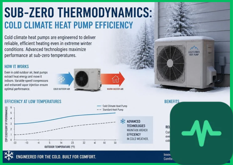
Coefficient of performance degradation at low ambient temperatures is driven by the widening thermodynamic gap between the low evaporating temperature and the high condensing temperature required for indoor space heating. Traditional heat pumps suffer from low COP values ( ) at
 (
 ), rendering them economically uncompetitive with direct electric resistance heating.
Vapor-injection heat pumps mitigate COP degradation through effective subcooling and volumetric compensation. By subcooling the liquid refrigerant entering the main evaporator expansion valve via an economizer or flash tank, the specific enthalpy change across the outdoor coil increases significantly. This ensures that every unit of electrical work consumed by the inverter compressor yields a higher thermal energy transfer rate to the indoor water or air distribution loop. Field data and academic engineering studies cited by the IEA confirm that vapor-injection heat pumps maintain operational COP values between  and
 even at ambient temperatures reaching
 (
 ).
Defrost Cycle Optimization and Frost Accumulation Dynamics
Operating heat pumps in sub-zero humid environments inevitably induces frost accumulation on the exterior aluminum fin-and-tube evaporator coils. Frost layers act as a thermal insulation barrier, increasing airside pressure drop, reducing heat transfer coefficients, and accelerating suction pressure decay.
Cold climate heat pumps utilize advanced predictive defrost algorithms coupled with vapor-injection compressors to minimize defrost cycle duration and energy penalties. When differential pressure sensors or optical frost detectors signal critical frost accumulation, the system reverses the cycle into cooling mode or utilizes hot-gas bypass injection to melt the frost layer rapidly. Vapor injection maintains high compressor mass flow during the defrost transition, shortening defrost intervals from 15 minutes down to less than 5 minutes and preserving indoor thermal comfort stability.


Comments (0)
Login to leave a comment.
No comments yet. Be the first to share your thoughts!