
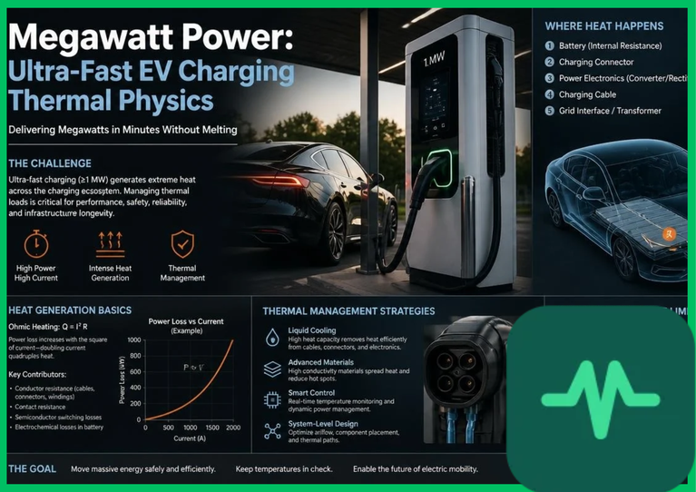
 ) at currents surpassing 500 amperes to 3,000 amperes introduces unprecedented thermal management challenges across power conversion electronics, umbilical cables, and lithium-ion battery pack architectures. Analyzing Joule heating dissipation, wide-bandgap semiconductor switching efficiencies, and cell-level thermal runaway mitigation is critical for evaluating ultra-fast charging performance.
Power Electronics and High-Voltage Silicon Carbide Inverters
The foundational electronic conversion challenge in megawatt-scale charging infrastructure resides in rectifying and stepping down medium-voltage grid power ( AC) into regulated direct current (DC) operating between 800 volts and 1,250 volts. Traditional silicon-based insulated-gate bipolar transistors (IGBTs) exhibit severe conduction and switching losses at high switching frequencies (
 ), generating excessive thermal waste that compromises power conversion efficiency.
Ultra-fast megawatt charging architectures deploy high-voltage silicon carbide ( ) metal-oxide-semiconductor field-effect transistors (MOSFETs) and Schottky diodes. Silicon carbide possesses a wide bandgap (
 compared to
 for silicon), an electric breakdown field strength ten times higher, and thermal conductivity triple that of traditional silicon. These physical properties enable power conversion in modular rectifier units to achieve operational efficiencies exceeding 95% to 97% while operating at switching frequencies up to
 .
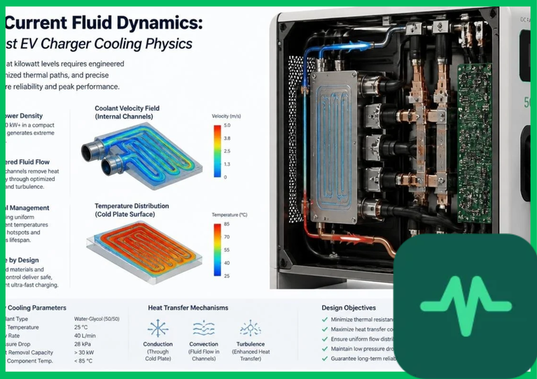
Despite high conversion efficiency, a 5% to 7% thermal loss rate during a nominal  power transfer generates
 to
 of waste heat directly within the charging cabinet. Managing this localized thermal load requires advanced forced-air and liquid-to-air heat exchangers to protect semiconductor junctions from exceeding maximum operating thresholds (
 [
 ]).
Liquid-Cooled Charging Cables and Conductor Thermal Limits
Delivering massive current loads ( ) through standard copper cables without liquid cooling would require conductor cross-sectional areas exceeding several square centimeters, rendering the umbilicals excessively heavy, stiff, and physically unmanageable for daily commercial operation. The electrical resistance (
 ) of a copper conductor generates internal Joule heating governed by the fundamental electrical power loss equation:
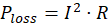
where  represents operating current (
 ) and
 is conductor resistance (
 ). As current increases quadratically, uncooled copper cables experience rapid internal temperature escalation, threatening insulation breakdown and severe burn hazards.
To resolve this thermal constraint, megawatt charging systems integrate active liquid-cooled charging cables. These specialized umbilicals incorporate micro-diameter internal channels through which a dielectric coolant fluid (such as an ethylene glycol-water mixture or specialized dielectric oil) is pumped continuously by closed-loop refrigeration units. The coolant absorbs heat directly from the inner boundaries of the copper current-carrying braids, maintaining cable operating temperatures below  to
 (
 to
 ) while enabling continuous current delivery up to 3,000 amperes through lightweight cable profiles.
Technical Data Specifications of Megawatt Charging Systems
| Megawatt Charging Parameter | Engineering & Power Electronics Specification Standard |
|---|---|
| Nominal Power Delivery Threshold |  to  continuous output |
| System DC Operating Voltage Range |  to  DC bus architecture |
| Maximum Continuous Current Rating |  to  via liquid-cooled umbilicals |
Power Conversion Efficiency ( ) | 95% to 97% utilizing Silicon Carbide ( ) MOSFETs |
| Charger Waste Heat Generation Rate |  to  thermal dissipation at  load |
| Maximum Battery C-Rate Charging |  to  peak electrochemical absorption |
| Liquid-Cooling Fluid Flow Rate | 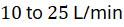 closed-loop dielectric circulation |
C-Rate Battery Degradation and Internal Joule Heating
While charging infrastructure handles megawatt-level power distribution externally, the receiving vehicle battery pack faces severe internal electrochemical stress governed by high C-rate charging dynamics. The C-rate defines the charge or discharge current relative to total nominal capacity; a  charging rate on a
 heavy-duty battery pack delivers a continuous
 power influx, fully replenishing the storage capacity in 15 minutes.
At these elevated C-rates, internal ionic resistance ( ) within the lithium-ion cell stack generates massive internal Joule heating (
 ). Lithium ions migrating through liquid organic carbonate electrolytes and intercalating into graphite or silicon-composite anodes encounter solid-state diffusion resistance. This resistance generates localized thermal spikes, driving internal cell temperatures upward at rates exceeding
 (
 ).
Unmitigated internal heating accelerates calendar and cycle aging, degrading the battery's state of health ( ). Prolonged exposure to temperatures above
 (
 ) during ultra-fast charging triggers structural degradation of cathode active materials, electrolyte decomposition, and irreversible capacity loss.
Thermal Runaway Mitigation and Active Liquid-Plate Cooling
Preventing thermal runaway during megawatt-scale ultra-fast charging requires sophisticated internal battery thermal management systems (BTMS). Modern commercial electric vehicle battery packs abandon passive air cooling entirely, deploying active liquid-plate cooling architectures where serpentine aluminum cooling plates are interleaved directly between prismatic or pouch battery cells.
During a megawatt charging event, thermal sensors embedded across the cell modules signal variable-speed chillers to circulate a glycol-water coolant through the battery plates at elevated flow rates (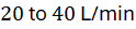 ). This forced convective cooling extracts thermal energy rapidly, maintaining cell operating temperatures within a tight thermal window of
 to
 (
 to
 ).
Furthermore, advanced battery management systems (BMS) implement dynamic current-tapering algorithms. As the battery state of charge (SoC) approaches 80%, ionic diffusion bottlenecks at the anode surface increase polarization resistance; the charging controller responds by stepping down current input exponentially, preventing excessive overpotential, eliminating lithium plating risks, and ensuring long-term electrochemical stability across thousands of ultra-fast charging cycles.
Comments (0)
Login to leave a comment.
No comments yet. Be the first to share your thoughts!