
 ) and reactive power (
 ). Evaluating four-quadrant power factor correction, grid frequency regulation, harmonic distortion filtering, and lithium-ion cycle life degradation is essential for analyzing bidirectional vehicle-to-grid inverter reactive power compensation.
Four-Quadrant Power Factor Correction and Reactive Power Mechanics
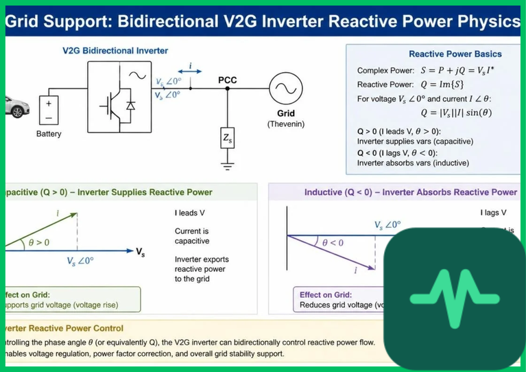
The foundational power-electronics capability enabling bidirectional vehicle-to-grid inverter reactive power compensation is four-quadrant operation. Unlike unidirectional chargers or single-quadrant inverters that transfer energy in one direction at near-unity power factor, a four-quadrant voltage-source inverter (VSI) modulates current phase angle ( ) relative to grid voltage (
 ) across all four quadrants of the complex
 -
 power plane: Quadrant I (
 ), Quadrant II (
 ), Quadrant III (
 ), and Quadrant IV (
 ).
Apparent power ( ), active power (
 ), and reactive power (
 ) follow fundamental AC circuit relationships:

where  denotes the phase displacement angle between voltage and current. When a distribution feeder experiences voltage sag under heavy inductive loading, a bidirectional inverter can shift current phase to supply capacitive reactive power (
 , volt-amperes reactive or
 ), raising local bus voltage without discharging net active kilowatt-hours from the battery pack. Conversely, during periods of high rooftop photovoltaic export that push feeder voltage upward, the inverter absorbs inductive reactive power (
 ) or modulates real power draw to stabilize voltage profiles within statutory grid tolerances (
 to
 of nominal RMS voltage).
Grid Frequency Regulation and Fast Inverter Response
Maintaining system frequency stability—typically around  or
 across synchronous grids—requires continuous balance between active power generation and load demand. Sudden generator trips or rapid shifts in industrial and residential demand create frequency deviations (
 ) that must be arrested within sub-second to multi-second windows before slow mechanical governor controls respond.
Power-electronic V2G inverters execute synthetic inertia and fast frequency response (FFR) by adjusting active power injection or charging curtailment within tens of milliseconds of detecting frequency drift via phase-locked loops (PLLs). Rating a bidirectional unit at  to
 (
 to
 ) for light-duty vehicles—or
 to
 (
 to
 ) at DC depots—allows aggregated fleets to deliver rapid active power modulation while operating across wide ambient temperatures (
 to
 [
 to
 ]). Reactive power compensation complements active frequency support by maintaining voltage stability during rapid power reversals, preventing inverter trip-outs caused by feeder impedance drops.
Technical Data Specifications of Bidirectional V2G Inverters
| Bidirectional V2G Parameter | Engineering & Power Electronics Specification Standard |
|---|---|
| Operating Quadrant Capability | Four-quadrant ( active power,  reactive power) |
| Typical AC Power Rating Envelope |  to  (  to  ) AC / up to  DC |
| Switching Topology & Devices | Silicon carbide ( ) MOSFETs or GaN bridge stages ( 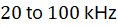 ) |
Total Harmonic Distortion ( ) |  to  at rated output under IEEE 1547 / IEC standards |
| Dynamic Step Response Time | 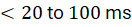 active/reactive setpoint tracking |
| Ambient Thermal Operating Range |  to  (  to  ) without derating |
| Grid Nominal Frequency Basis |  or  with phase-locked loop synchronization |
Harmonic Distortion Filtering and Wide-Bandgap Switching
High-frequency pulse-width modulation (PWM) switching in silicon carbide ( ) or gallium nitride (
 ) inverters introduces high-order current harmonics into the AC distribution network. Unfiltered switching harmonics distort voltage waveforms, induce extra heating in distribution transformers and neutral conductors, and trigger nuisance tripping of sensitive grid relays.
To enforce harmonic distortion filtering, bidirectional V2G inverters incorporate passive  (inductor-capacitor-inductor) output filters paired with active damping control algorithms. The
 filter attenuates high-frequency switching components around the carrier frequency while keeping fundamental frequency voltage drop small. Combining wide-bandgap semiconductors with multi-level topologies—such as T-type or neutral-point-clamped (NPC) three-level inverters—reduces switching losses and lowers current total harmonic distortion (
 ) below 3% to 5%, preserving power quality across both active and reactive power modes.
Lithium-Ion Cycle Life Degradation and Thermal Stress
Providing grid services through bidirectional energy exchange exposes traction batteries to additional current throughput and partial cycling that can accelerate lithium-ion cycle life degradation if poorly controlled. Every charge-discharge micro-cycle drives lithium-ion intercalation and de-intercalation across layered nickel-manganese-cobalt ( ) or lithium iron phosphate (
 ) cathodes and graphite anodes, contributing incrementally to solid electrolyte interphase (SEI) film growth and internal impedance rise.
Empirical battery aging studies in engineering literature show that degradation severity depends heavily on state of charge (SoC) window, depth of discharge, C-rate, and cell temperature ( to
 [
 to
 ] optimal). Deep cycling at high SoC (
 ) or low temperatures (
 [
 ]) accelerates capacity fade, whereas shallow cycling around mid-SoC (
 to
 ) at moderate C-rates (
 ) limits incremental aging. Furthermore, pure reactive power compensation (
 -only mode) circulates energy within the inverter DC-link capacitor and grid network rather than deep-cycling the battery pack, offering grid voltage support with minimal direct electrochemical wear on battery cells.

Comments (0)
Login to leave a comment.
No comments yet. Be the first to share your thoughts!