
Electromagnetic Induction and Resonant Coupling Physics
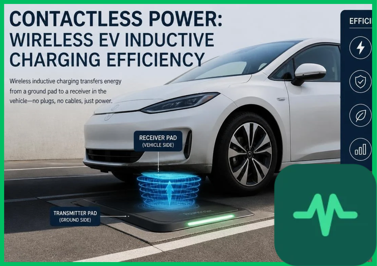
The foundational physical principle governing wireless power transfer is Faraday's law of electromagnetic induction coupled with Ampere-Maxwell equations. An inductive charging system comprises two loosely coupled magnetic coils: a primary transmitting coil embedded in the pavement and a secondary receiving coil mounted on the underbody of the electric vehicle.
When high-frequency alternating current—typically ranging from  to
 in accordance with SAE J2954 standards—flows through the primary transmitter coil, it generates an oscillating magnetic flux (
 ) that links with the secondary receiver coil. The induced electromotive force (
 ) in the secondary coil is proportional to the rate of magnetic flux linkage change:
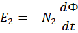
where  represents the number of turns in the secondary receiver coil. Because the air gap between the ground pad and vehicle underbody (
 to
 [
 ]) introduces high magnetic leakage flux and low magnetic coupling coefficients (
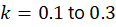 ), uncompensated inductive coils suffer from severe reactive power losses and low transmission efficiency.
To overcome this leakage reactance, wireless power transfer systems integrate capacitor compensation networks (Series-Series [SS], Series-Parallel [SP], Parallel-Series [PS], or Parallel-Parallel [PP] topologies) on both primary and secondary sides. Tuning these capacitor-inductor networks to resonate precisely at the operating frequency neutralizes leakage reactance, elevating overall power transfer efficiency above 90% to 94%.
Power Conversion Architecture and High-Frequency Inverters
Executing high-efficiency wireless power transfer requires multi-stage power conversion electronics operating at high frequencies. Utility-scale alternating current ( or
 ) is first rectified into direct current (DC) and subsequently inverted into high-frequency AC (
 ) using wide-bandgap semiconductor switches, specifically silicon carbide (SiC) MOSFETs or gallium nitride (GaN) transistors.
High-frequency inversion is necessary because inductive coupling efficiency scales proportionally with operating frequency ( ). Operating at
 allows engineers to reduce physical coil dimensions and ferrite core mass while maintaining high power transfer densities (
 to
 for residential/commercial stationary pads, scaling up to
 to
 for heavy-duty dynamic highway charging). However, high switching frequencies induce severe electromagnetic interference (EMI) and core eddy current losses within the ferrite shielding plates, requiring advanced thermal management and magnetic shielding enclosures.
Technical Data Specifications of Wireless Inductive Charging Parameters
| Wireless EV Charging Parameter | Engineering Specification Standard |
|---|---|
Operating Resonant Frequency ( ) |  nominal (SAE J2954 standardized band) |
| Air Gap Separation Distance |  to  (  ) ground-to-vehicle |
Magnetic Coupling Coefficient ( ) |  to  loose coupling threshold |
Power Transfer Efficiency ( ) | 90% to 94% DC-to-DC grid-to-battery efficiency |
| Resonant Compensation Topologies | Series-Series (SS) / Series-Parallel (SP) networks |
| Semiconductor Switching Technology | Silicon Carbide (SiC) / GaN high-frequency MOSFETs |
| Electromagnetic Leakage Field Limits |  magnetic flux density at  boundary |
Coil Misalignment Sensitivity and Air Gap Losses
A major operational challenge constraining wireless inductive charging is sensitivity to spatial coil misalignment. During manual parking or autonomous vehicle positioning, lateral ( -axis), longitudinal (
 -axis), and angular misalignments between the primary transmitter pad and secondary receiver pad occur frequently.
Spatial displacement degrades mutual inductance ( ), causing resonant frequency detuning and a sharp drop in power transfer efficiency. When coils are misaligned by more than
 (
 ), leakage magnetic fluxes expand outward, increasing eddy current heating in surrounding aluminum vehicle chassis components and reducing system efficiency by 5% to 15%. Modern wireless charging systems deploy closed-loop active tuning controllers and magnetic position-sensing beacons to dynamically adjust operating frequency or phase angles, compensating for physical misalignment and sustaining stable power delivery.
Electromagnetic Shielding and Human Safety Compliance
Generating high-intensity magnetic fields ( ) beneath an electric vehicle introduces strict safety compliance challenges regarding electromagnetic field (EMF) human exposure limits and cardiac pacemaker interference. International safety guidelines established by the International Commission on Non-Ionizing Radiation Protection (ICNIRP) mandate strict magnetic flux density thresholds (typically
 ) at a
 (
 ) perimeter around the vehicle.
Engineers suppress stray magnetic fields by installing high-permeability ferrite bar arrays beneath the primary and secondary coils to channel magnetic flux lines, coupled with external aluminum or copper shielding plates that generate counter-electromagnetic fields via eddy currents. Furthermore, active foreign object detection (FOD) and living object detection (LOD) sensor suites—comprising radar, optical infrared cameras, and capacitive proximity grids—scan the air gap prior to high-power activation. If a metallic object (such as a coin or aluminum foil) or biological entity enters the electromagnetic field, system controllers instantly terminate power transfer to prevent severe inductive heating.
The Final Take
Mastering wireless ev inductive charging efficiency advances contactless electric mobility by overcoming loose magnetic coupling and air gap leakage reactance. Citing IEA electric mobility assessments and power electronics literature, resonant capacitor compensation networks and high-frequency silicon carbide inverters elevate wireless power transfer efficiencies above 90%. By mitigating coil misalignment losses and enforcing rigorous electromagnetic shielding, wireless inductive charging establishes a viable alternative for automated stationary and dynamic EV energy transfer.
Comments (0)
Login to leave a comment.
No comments yet. Be the first to share your thoughts!