
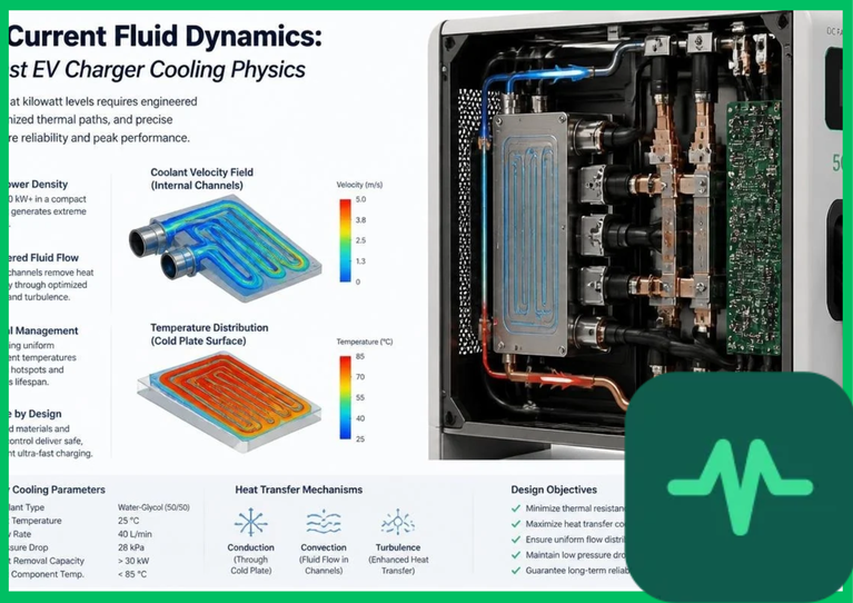
 to
 requires massive electrical currents that can surpass
 through standard charging cables. Without advanced thermal management, ohmic heating (
 ) within copper conductor strands would elevate cable temperatures beyond safe operational limits (
 [
 ]), risking cable insulation degradation and thermal breakdown. Integrating forced liquid cooling systems circulates specialized dielectric coolants directly through the charging cable assembly, maintaining copper conductor temperatures within optimal thermal thresholds and enabling high-current density power delivery.
Ohmic Resistance Realities and Conductor Joule Heating
The foundational thermodynamic challenge governing ultra-fast EV charging is the exponential rise of internal resistive heating within cable conductors as charging currents increase. The thermal energy generation rate ( ) per unit length of a conductor is expressed mathematically by Joule's first law:
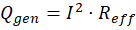
where  represents the direct electrical current flowing through the cable, and
 denotes the effective AC/DC electrical resistance of the multi-strand copper conductors at operating temperature.
To prevent excessive voltage drop and heavy mechanical weight, traditional air-cooled charging cables require massive copper cross-sectional areas (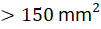 [
 ]) to handle currents above
 . However, increasing copper cross-section beyond specific physical thresholds makes charging cables excessively heavy, stiff, and ergonomically unmanageable for vehicle operators. Liquid-cooled charging cables bypass this physical limitation by reducing copper conductor cross-sectional areas down to
 to
 (
 ), relying on continuous fluid convection to extract heat and maintain flexible cable handling.
Dielectric Coolant Fluid Dynamics and Heat Transfer Coefficients
Executing efficient thermal extraction requires circulating specialized dielectric heat transfer fluids through coaxial channels integrated directly inside the charging cable and connector plug interface. Common coolant fluids include synthetic polyalphaolefins (PAO), ethylene glycol-water mixtures, or specialized fluorochemical dielectric liquids possessing high thermal conductivities, low dynamic viscosities, and high electrical breakdown voltage thresholds ( ).
The convective heat transfer rate ( ) from the copper conductor surface to the flowing dielectric liquid is governed by Newton's law of cooling:

where  represents the convective heat transfer coefficient,
 is the internal wetted surface area,
 is copper winding temperature, and
 is the bulk coolant temperature.
Forced turbulent fluid circulation achieved via high-pressure variable-speed pumps elevates convective heat transfer coefficients ( ) to values exceeding
 to
 . This rapid thermal extraction ensures that copper conductor temperatures remain below
 (
 ) even when sustaining continuous
 loads in
 (
 ) ambient environmental conditions.
Technical Data Specifications of Ultra-Fast EV Charger Cooling Parameters
| Ultra-Fast EV Charger Cooling Parameter | Engineering Specification Standard |
|---|---|
| Maximum Charging Current Threshold |  to  continuous DC output |
| Cooling Cable Copper Conductor Area |  to  (  ) |
| Dielectric Fluid Breakdown Voltage |  electrical insulation threshold |
Convective Heat Transfer Coefficient ( ) |  to  |
| Maximum Conductor Operating Temp |  to  (  to  ) |
| Coolant Pump Flow Rate Range |  to  closed-loop circulation |
| Power Cabinet Semiconductor Switches | Silicon Carbide (SiC) MOSFET / IGBT modules |
Power Electronics Thermal Dissipation and Semiconductor Cooling
Beyond charging cables, ultra-fast EV charging infrastructure requires rigorous thermal management within the stationary power conversion cabinet. Grid-tied power conversion units rectify alternating current (AC) line voltage ( to
 AC) into regulated high-voltage direct current (
 to
 DC) via high-frequency active power factor correction (PFC) rectifiers and DC-DC resonant dual-active-bridge converters.
Modern ultra-fast chargers utilize wide-bandgap silicon carbide (SiC) MOSFET power semiconductor switches operating at high switching frequencies ( to
 ) to minimize electrical conversion losses. Despite high conversion efficiencies (
 ), a
 power cabinet dissipates approximately
 of thermal waste energy across semiconductor junction nodes. Power modules are mounted directly onto extruded aluminum liquid cold plates bonded with copper micro-channel fins, rejecting thermal energy through closed-loop glycol-water heat exchangers equipped with variable-speed condenser fans.
Flow Rate Optimization, Pressure Drop, and Safety Interlocks
Managing fluid dynamics within long, flexible charging cables requires precise balancing between coolant flow rates and hydraulic pressure drops. As dielectric fluid is pumped through narrow coaxial channels across a  to
 (
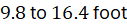 ) cable length, frictional resistance induces a significant pressure drop (
 ) governed by the Darcy-Weisbach equation:
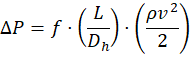
where  represents the Darcy friction factor,
 is hose length,
 is hydraulic diameter,
 is fluid density, and
 is fluid velocity. Excessive flow restriction increases pump power consumption and creates mechanical stress on flexible outer jacketing.
To guarantee operational safety, liquid-cooled charging systems integrate redundant flow sensors, pressure transducers, and optical temperature telemetry directly into the connector plug. If coolant flow drops below critical safety thresholds or if fluid temperature spikes due to pump failure, the master charging controller terminates high-current DC output within milliseconds, preventing catastrophic thermal runaway or connector melting.
The Final Take
Mastering ultra-fast ev charger liquid cooling physics secures the high-current density and thermal stability required for next-generation electric vehicle charging infrastructure. Citing IEA charging technology reports, circulating specialized dielectric coolants through lightweight copper conductors suppresses ohmic heating and maintains safe operational temperatures during  charging sessions. By combining forced fluid dynamics with silicon carbide power electronics and automated safety interlocks, liquid-cooled charging architecture establishes an indispensable foundation for rapid EV adoption.

Comments (0)
Login to leave a comment.
No comments yet. Be the first to share your thoughts!