Kinetic Energy Recovery and Deceleration Physics
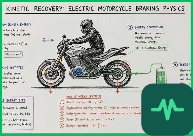
The foundational physical principle underlying regenerative braking is the conversion of vehicular kinetic energy into electrical energy during deceleration. The total kinetic energy ( ) stored in a moving electric motorcycle is formulated mathematically as:
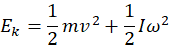
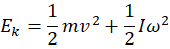
where  represents the combined mass of the motorcycle and rider,
 denotes forward linear velocity,
 is the rotational moment of inertia of the wheels and motor rotor, and
 is the angular velocity of the rotating assemblies.
When the rider rolls off the throttle or applies regenerative brake pressure, the motor controller commands negative electromagnetic torque ( ). This braking torque exerts a retarding force on the rear wheel, decelerating the vehicle mass and forcing the electric motor to operate as a generator. The mechanical power (
 ) extracted from the drivetrain is defined by the product of braking torque and angular speed:
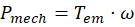
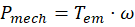
This extracted mechanical power is transmitted through the motor rotor windings, inducing back electromotive force (back-EMF) and generating alternating current (AC) electricity within the stator coils.
Inverter Four-Quadrant Operation and Power Conversion
Converting variable-frequency AC electricity generated by the decelerating motor into direct current (DC) suitable for lithium-ion battery storage requires advanced power electronics. Electric motorcycle inverters utilize insulated-gate bipolar transistors (IGBTs) or silicon carbide (SiC) MOSFET switches capable of four-quadrant operation.
During motoring (acceleration), the inverter operates in quadrants I and III, supplying variable voltage and frequency to generate positive torque and rotation. During regenerative braking, the inverter switches to quadrants II and IV, where the phase voltage leads the phase current by more than 90 degrees. Pulse-width modulation (PWM) algorithms control the switching duty cycle, acting as a synchronous boost converter. This converter steps up the low alternating voltage generated by the spinning motor windings to match or exceed the high DC bus voltage of the battery pack (typically  to
 ), ensuring smooth, controlled current flow back into the lithium-ion cells.
Brushless Motor Control and Field-Oriented Control Algorithms
Executing precise regenerative braking requires advanced digital signal processor (DSP) algorithms, primarily field-oriented control (FOC) or sensorless vector control. In a permanent magnet synchronous motor, rotor position is tracked continuously via high-resolution resolvers or calculated via back-EMF observers.
When braking is initiated, the motor controller adjusts the stator magnetic field vector ahead of the rotor position, creating a negative d-axis and q-axis current injection. This magnetic alignment maximizes braking torque generation without inducing current spikes or torque ripple. Furthermore, adaptive slip compensation and current-limiting feedback loops prevent excessive regeneration torque at high speeds, ensuring that rear-wheel traction limits are not exceeded on low-friction road surfaces, which could otherwise induce dangerous rear-wheel lockup or skid conditions.
Technical Data Specifications of Regenerative Braking Parameters
| Electric Motorcycle Braking Parameter | Engineering Specification Standard |
|---|---|
| Kinetic Energy Recovery Efficiency | 10% to 25% total urban range extension |
| Inverter Switching Architecture | Silicon Carbide (SiC) / IGBT four-quadrant PWM |
| Battery Pack Operating Voltage Range |  to  DC bus architecture |
| Regenerative Deceleration Force |  to  negative acceleration threshold |
| Motor Topologies Supported | Permanent Magnet Synchronous Motor (PMSM) / BLDC |
| Maximum Regenerative Charge Current |  to  safe battery acceptance rate |
| Mechanical Brake Pad Wear Reduction | 40% to 60% extended friction component lifespan |
Battery State of Charge and High-Rate Charging Limits
While aggressive regenerative braking maximizes energy recovery, returning high electrical currents into lithium-ion battery packs requires strict adherence to electrochemical safety thresholds. High-rate pulse charging during rapid deceleration generates internal joule heating ( ) within the battery cells and accelerates lithium plating on graphite anodes if cell voltage exceeds safe electrochemical limits.
Battery management systems (BMS) monitor cell temperature, internal resistance, and state of charge (SoC) in real time. When the battery pack approaches 90% to 95% state of charge, the BMS restricts regenerative braking torque gradually to prevent overvoltage conditions. Similarly, at sub-zero operating temperatures (below  [
 ]), lithium-ion ionic diffusion rates drop sharply, forcing the motor controller to attenuate regenerative braking power to prevent catastrophic anode degradation.
Thermal Management and Power Dissipation Realities
Energy conversion during regenerative braking is constrained by thermodynamic efficiency limits. The round-trip energy conversion efficiency ( ) governing kinetic energy recovery is the product of mechanical drivetrain efficiency, motor generation efficiency, inverter conversion efficiency, and battery coulombic charging efficiency:


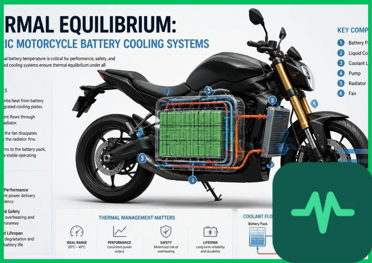
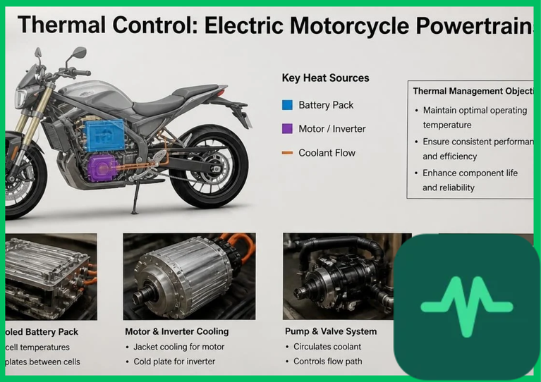
Practical electric motorcycle powertrains achieve overall regenerative efficiencies between 60% and 75%. The remaining 25% to 40% of dissipated energy is converted into thermal waste heat within the motor stator windings and power inverter semiconductor junctions. Continuous high-speed braking on steep mountain descents can elevate motor stator temperatures rapidly. To prevent thermal breakdown of copper winding insulation, high-performance electric motorcycles integrate liquid cooling jackets around the motor housing or rely on aluminum finned heat sinks connected to the inverter baseplate.
The Final Take
Mastering electric motorcycle regenerative braking efficiency optimizes urban energy recovery and extends the operational range of electric two-wheelers. Citing IEA electric mobility assessments and power electronics literature, four-quadrant inverter control and field-oriented motor algorithms capture up to 25% of kinetic deceleration energy. By balancing high-rate battery charging limits with advanced thermal management, regenerative braking systems deliver an indispensable technical foundation for high-efficiency electric motorcycle engineering.
Comments (0)
Login to leave a comment.
No comments yet. Be the first to share your thoughts!