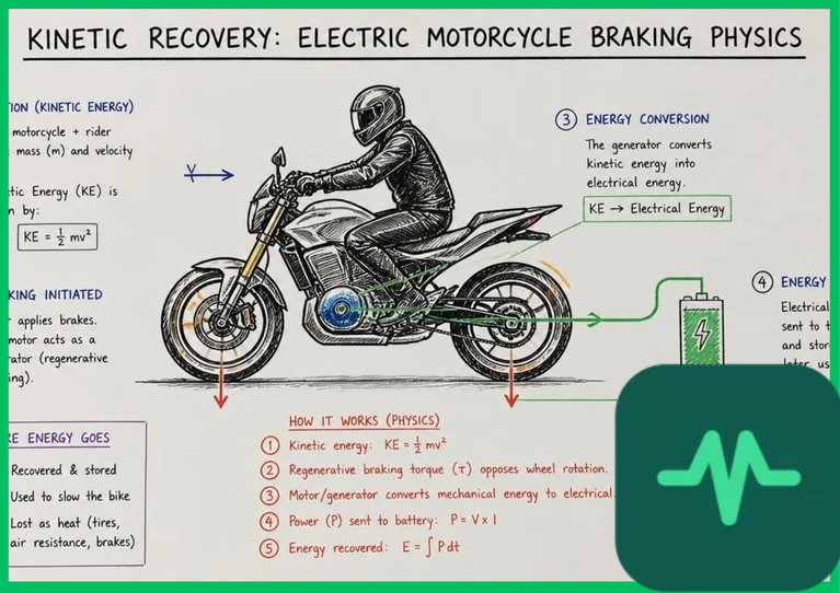
Kinetic Energy Physics and Deceleration Equations
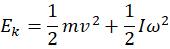
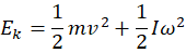
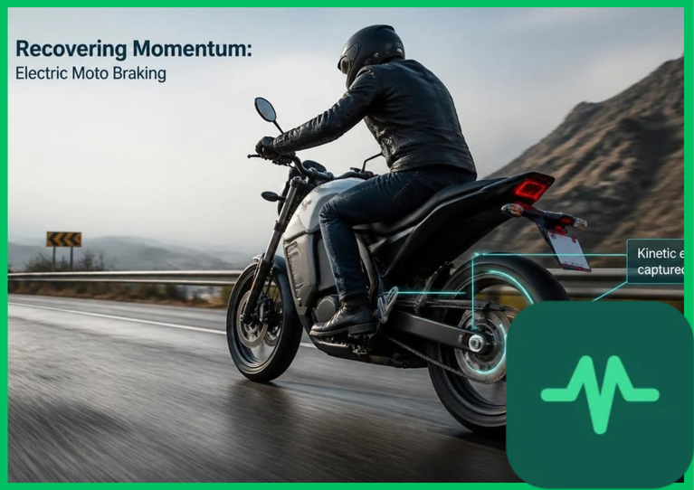
The fundamental physical principle governing regenerative braking is the conversion of translational and rotational kinetic energy into electrical work during deceleration. The total kinetic energy ( ) of an electric motorcycle of mass
 traveling at velocity
 , combined with the rotational inertia (
 ) of its wheels and motor rotor rotating at angular velocity
 , is expressed as:
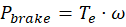
When a rider initiates deceleration, the electronic control unit (ECU) commands the motor inverter to apply a negative electromagnetic torque ( ). The braking power (
 ) extracted from the vehicle drivetrain is proportional to the product of braking torque and rotational speed (
 ). In conventional internal combustion motorcycles, this mechanical energy is entirely dissipated as thermal waste through brake pad and rotor friction, generating surface temperatures exceeding
 (
 ). In contrast, electric motorcycle kinetic energy recovery systems (KERS) exert controlled electromagnetic resistance, converting kinetic energy into multi-phase alternating current electrical power.
Brushless Motor Deceleration and Generator Mode Physics
Transitioning an electric motorcycle's permanent-magnet synchronous motor (PMSM) from motoring mode to generation mode requires altering the rotor-stator electromagnetic phase relationship. During motoring, the stator magnetic field leads the rotor permanent magnet flux by a positive torque angle ( ), creating motoring torque that accelerates the vehicle. During regenerative braking, the inverter shifts the stator current phase angle such that the stator magnetic field lags the rotor flux (
 ). This phase reversal transforms the electric motor into a synchronous generator.
The rotating permanent magnets induce back-electromotive force (back-EMF) voltages across the stator windings. As the rotor decelerates, the magnitude of the induced back-EMF is maintained below the maximum DC bus voltage limit of the battery pack through field-weakening algorithms, ensuring stable electrical current generation without damaging downstream power electronics.
Electronic Braking Control and Field-Oriented Control (FOC)
Precise execution of brushless motor deceleration relies on advanced electronic braking control algorithms executed by digital signal processors (DSPs) via field-oriented control (FOC). FOC decouples the stator current vector into two orthogonal components: the direct-axis current ( ) aligned with the rotor magnetic flux, and the quadrature-axis current (
 ) responsible for electromagnetic torque generation.
During regenerative braking, the motor controller commands a negative quadrature-axis current ( ), generating precise braking torque that scales linearly with throttle twist-grip release or brake lever travel. Simultaneously, the inverter pulse-width modulation (PWM) switches—fabricated from wide-bandgap silicon carbide (
 ) semiconductors—boost the alternating current generated by the stator up to a voltage level exceeding the instantaneous terminal voltage of the lithium-ion battery pack, enabling smooth energy transfer into high-voltage cells.
Technical Data Specifications of Regenerative Braking Parameters
| Braking Parameter | Engineering Specification Range |
|---|---|
| Regenerative Braking Torque |  to  (  to  ) |
| Maximum Deceleration Rate |  to  pure electromagnetic braking |
| Inverter Rectification Frequency |  to  PWM switching |
| Urban Range Extension Yield | 10% to 25% increased operational distance |
| Round-Trip Energy Efficiency | 60% to 75% mechanical-to-electrical recovery |
| Maximum Battery Charge Current |  to  instantaneous acceptance |
Battery Acceptance Limits and State of Charge Restrictions
While high-rate energy recapture is desirable, battery charge acceptance limits restrict the maximum allowable regenerative braking current. Pumping excessive electrical current into a lithium-ion battery pack—particularly when the cell state of charge (SoC) exceeds 90% or when ambient temperatures drop below  (
 )—triggers severe lithium plating on the graphite anode surface.
Lithium plating occurs when lithium ions reduce into metallic dendrites rather than intercalating into the graphite crystal lattice, permanently destroying active cyclable lithium inventory and increasing internal resistance ( ). Advanced battery management systems (BMS) continuously monitor cell voltage, internal temperature, and state of health (SoH), dynamically modulating the maximum allowable regenerative braking torque to prevent overvoltage conditions and protect energy storage assets.
Efficiency Realities and Range Extension Metrics
Quantifying the net efficiency of electric motorcycle kinetic energy recovery systems requires evaluating round-trip conversion losses across mechanical transmission gears, motor electromagnetic conversion, inverter rectification, and battery internal resistance. The round-trip energy efficiency ( ) of the recovery loop is expressed as:


Modern high-performance electric motorcycles achieve aggregate round-trip recovery efficiencies between 60% and 75%. While thermodynamic losses preclude 100% energy recovery, capturing kinetic energy during urban deceleration reduces friction brake wear by up to 70% while extending vehicle range significantly. Citing automotive engineering literature and electric vehicle efficiency analyses, regenerative braking stands as an essential electromechanical subsystem for optimizing total energy consumption across sustainable electric transport architectures.


Comments (0)
Login to leave a comment.
No comments yet. Be the first to share your thoughts!