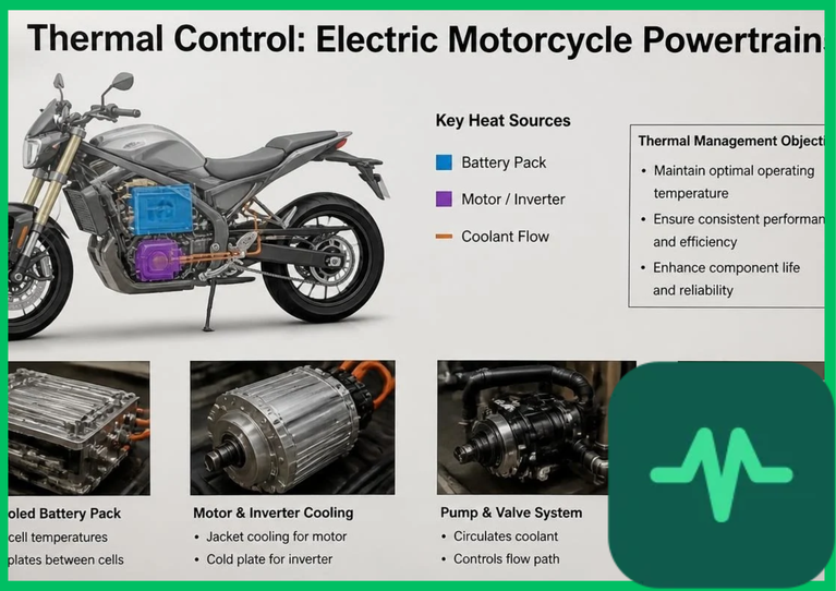
 to
 (
 to
 ) from compact structural packages. Managing intense thermal energy generation across lithium-ion battery packs, permanent-magnet synchronous motors, and high-frequency inverters requires rigorous engineering control over fluid dynamics, junction temperatures, heat transfer coefficients, and closed-loop thermal architecture.
High-Discharge Battery Cooling and Joule Heating Physics ( )
Electric motorcycle battery packs experience severe thermal stress during rapid acceleration and regenerative braking events, where discharge and charge currents frequently exceed  to
 rates. The fundamental physical driver of battery thermal energy generation is internal Joule heating, quantified by the combined resistive and electrochemical polarization equation:
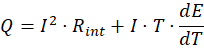
where  represents operating current,
 denotes internal cell resistance,
 is absolute temperature in Kelvin, and
 represents the entropy change coefficient of the electrochemical reaction. Joule heating (
 ) scales exponentially with current, causing internal cell temperatures to rise rapidly during aggressive throttle inputs.
To prevent accelerated solid-electrolyte interphase (SEI) degradation and lithium plating, advanced electric motorcycles abandon passive air cooling in favor of active liquid cooling. Direct liquid-cooled cold plates—manufactured from extruded aluminum alloys featuring internal microchannel fluid paths—are clamped directly to prismatic or pouch lithium-ion cells using thermally conductive, electrically insulating gap-filler pads. These cold plates circulate water-glycol mixtures or dielectric coolants, maintaining uniform cell temperature distributions within the optimal electrochemical window of  to
 (
 to
 ) and restricting inter-cell thermal gradients to less than
 (
 ).
Liquid Cooled Electric Motors and Rotor Thermal Dynamics
Electric motorcycle propulsion relies primarily on high-power-density permanent-magnet synchronous motors (PMSM) operating at rotational speeds exceeding 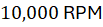 to
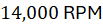 . High rotational speeds combined with high electromagnetic torque generate intense thermal loads within both stator windings and rotor assemblies.
Stator copper losses ( resistive heating within copper wire coils) represent the primary internal thermal source. If stator winding temperatures exceed thermal class insulation limits (typically
 to
 or
 to
 for Class H enamel), electrical insulation degrades, causing short circuits and catastrophic motor failure. Furthermore, rotor assemblies containing neodymium-iron-boron (
 ) permanent magnets face severe operational risks; temperatures exceeding
 to
 (
 to
 ) induce permanent magnetic demagnetization and torque output collapse.
To mitigate these thermal risks, high-performance electric motorcycles utilize liquid cooled electric motors incorporating direct stator slot cooling or integrated outer water jackets. Advanced designs circulate automatic transmission fluid (ATF) or specialized dielectric oils directly over end-windings, eliminating thermal contact resistance between copper conductors and stator iron cores, and ensuring continuous peak torque delivery without thermal throttling.
Inverter Thermal Dissipation and Silicon Carbide (SiC) Switching
Power electronics inverters convert direct current (DC) from the battery pack into variable-frequency alternating current (AC) to drive the traction motor via pulse-width modulation (PWM) switching frequencies ranging from  to
 . Inverter semiconductor switches experience two distinct loss mechanisms: conduction losses and switching losses.
Traditional silicon insulated-gate bipolar transistors (IGBTs) exhibit high switching losses at high frequencies, generating substantial thermal energy within narrow silicon junctions. Modern high-performance electric motorcycles integrate wide-bandgap silicon carbide ( ) MOSFET semiconductor modules. Silicon carbide power switches possess superior material properties, including a wide bandgap energy (
 vs.
 for silicon) and high thermal conductivity, which reduce switching power losses by over 50% compared to legacy silicon IGBTs.
Managing thermal dissipation in SiC power modules requires mounting semiconductor dies onto direct-bonded copper (DBC) ceramic substrates bonded to pin-fin aluminum baseplates. High-velocity coolant impingement flowing across these pin-fins maximizes convective heat transfer coefficients, maintaining semiconductor junction temperatures below  (
 ) under maximum acceleration loads.
Technical Data Specifications of Powertrain Thermal Parameters
| Powertrain Thermal Parameter | Engineering Specification Range |
|---|---|
| Battery Operating Temperature |  to  (  to  ) optimal window |
| Max Inter-Cell Temperature Gradient |  (  ) variation across pack |
| Stator Insulation Thermal Class | Class H ( to  /  to  ) |
| Permanent Magnet Demagnetization Limit |  to  (  to  ) |
| Inverter SiC Junction Temperature Limit | Maximum  to  (  to  ) |
| Inverter PWM Switching Frequency |  to  operational range |
| Coolant Loop Operating Pressure |  to  (  to  ) |
Closed-Loop Thermal Fluid Management and Pumping Parasitics
Coordinating thermal management across the battery, motor, and inverter requires a sophisticated closed-loop fluid management architecture. Most high-performance electric motorcycles deploy dual-loop thermal circuits: a low-temperature loop dedicated to cooling the high-discharge battery pack (maintaining tighter temperature tolerances), and a high-temperature loop servicing the traction motor and power inverter.
The thermal transport fluid typically comprises a 50/50 volumetric mixture of ethylene glycol and deionized water, or specialized low-viscosity synthetic dielectric fluids for direct-contact applications. Variable-speed brushless DC electric water pumps modulate fluid flow rates based on real-time thermistor telemetry embedded across battery modules and semiconductor heat sinks.
While active liquid pumping introduces minor parasitic electrical loads ( to
 auxiliary power consumption), the thermodynamic benefits far outweigh the auxiliary energy penalty. Maintaining optimal thermal equilibrium across all powertrain components prevents localized overheating, preserves battery state-of-health (SoH) over thousands of charge-discharge cycles, and guarantees sustained high-speed vehicle performance without thermal derating.
Comments (0)
Login to leave a comment.
No comments yet. Be the first to share your thoughts!