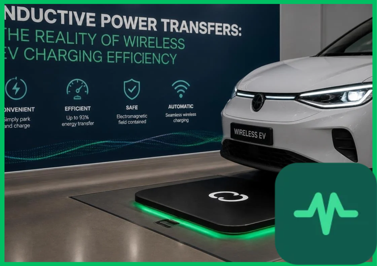
Electromagnetic Induction and Mutual Inductance
At the core of wireless power transfer is Faraday's law of induction and Ampere's circuital law. A high-frequency inverter converts grid AC power into high-frequency alternating current, which flows through a primary transmitter coil embedded in the pavement or garage floor. This alternating current generates a fluctuating magnetic flux density ( ). When aligned with a secondary receiver coil mounted on the vehicle underbody, the magnetic flux induces an electromotive force (EMF) across the secondary winding.
Coupling efficiency is dictated by the mutual inductance ( ) between the transmitter coil (
 ) and receiver coil (
 ), quantified by the dimensionless coupling coefficient (
 ):


In practical electric vehicle installations, air gaps range from  to
 (
 to
 ). This expansive air gap results in loose magnetic coupling, yielding coupling coefficients typically ranging from 0.15 to 0.40. Without reactive power compensation, loose coupling causes massive leakage inductance, restricting power transfer capability to negligible levels.
Resonant Compensation Topologies and Quality Factors
To overcome high leakage inductance, inductive power transfer systems incorporate capacitor networks to establish electrical resonance matching the operating frequency. Resonant compensation topologies dictate voltage-current phase relationships and system load sensitivity.
- Series-Series (SS): Both primary and secondary coils feature series-connected capacitors. Resonant frequency is independent of load resistance, making SS topology ideal for constant current output profiles.
- Series-Parallel (SP): Primary circuit uses series compensation; secondary uses parallel compensation. Acts as a current-to-voltage converter, stabilizing output voltage under varying battery states of charge.
- Parallel-Series (PS): Primary uses parallel compensation; secondary uses series compensation, maintaining constant current characteristics at the receiver output.
- Parallel-Parallel (PP): Both circuits feature parallel capacitors, sensitive to load variations but providing high voltage gains under open-circuit conditions.
The performance of these resonant circuits depends on the quality factor ( ) of the coils:


where  is angular frequency in radians per second,
 is coil inductance in Henries (
 ), and
 is equivalent series resistance in Ohms (
 ). High-permeability ferrite cores and Litz wire—composed of many thin, individually insulated strands—are utilized to minimize skin effect and proximity effect AC resistance, driving coil quality factors above 150 at operating frequencies between
 and
 .
Frequency Selection and Electromagnetic Compatibility (EMC)
International standardization bodies, including the Society of Automotive Engineers (SAE J2954) and the International Electrotechnical Commission (IEC 61980), mandate specific frequency bands for wireless EV charging to prevent electromagnetic interference (EMI) with radio communications, medical devices, and military frequencies. The designated frequency band centers at  (
 tolerance).
Operating at  introduces severe electromagnetic compatibility challenges. High-frequency magnetic fields generate parasitic eddy currents in nearby vehicle chassis components, reinforcing resistive heating and energy losses. To contain stray magnetic fields, engineers install aluminum or copper shielding plates lined with manganese-zinc (
 ) ferrite tiles beneath the transmitter and receiver coils. These ferrite cores guide magnetic flux lines, while conductive shielding plates cancel out fringe magnetic fields via counter-electromotive force, ensuring compliance with IEEE C95.1 human exposure safety limits for electromagnetic field strength.
Thermal Dissipation and Power Electronics Losses
Power conversion efficiency in wireless systems is constrained by thermal dissipation across multiple conversion stages. The grid-to-battery power transfer chain incurs losses across four distinct subsystems:
| Grid Inverter | High-frequency DC-AC inverters utilize wide-bandgap semiconductors, such as Silicon Carbide (SiC) MOSFETs or Gallium Nitride (GaN) HEMTs, achieving switching efficiencies exceeding 98.5%. |
| Transmitter Coil and Matching Network | Copper resistive losses and core hysteresis in ferrite plates generate thermal energy, raising operating temperatures up to  to  (  to  ). |
| Receiver Coil and Rectifier | Secondary-side high-frequency AC is converted to DC via synchronous rectification bridges, experiencing forward voltage drop and switching losses. |
| Battery Management System (BMS) Interconnect | Final DC charging stage regulates voltage input to the lithium-ion cell packs. |
Thermal management requires active liquid cooling loops or aluminum heat sinks integrated directly into the floor-pad assembly. Excessive temperatures accelerate ferrite core saturation, dropping permeability and degrading mutual inductance.
Static vs. Dynamic Wireless Charging Realties
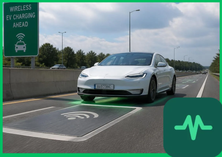
Wireless power transfer operates in two distinct operational modes: stationary (static) charging and in-motion (dynamic) charging. Static systems charge parked passenger vehicles, municipal buses, or automated delivery fleets over stationary ground pads. Dynamic wireless charging embeds transmitter coils continuously beneath highway lanes, transferring power to electric vehicles while traveling at highway speeds ( or
 ).
While dynamic wireless charging theoretically eliminates massive battery weight requirements by enabling continuous replenishment, infrastructure capital expenditure remains prohibitive. Constructing embedded roadway power transmitters requires cutting, waterproofing, and reinforcing highway asphalt across thousands of kilometers, incurring installation costs exceeding millions of dollars per lane-mile. Furthermore, lateral and longitudinal vehicle misalignment during highway travel drops coupling efficiency below 70%, amplifying reactive power demands on grid distribution transformers.
Empirical Research and Efficiency Metrics
Academic research consortia and life-cycle analyses published by the United Nations Environment Programme (UNEP) evaluate inductive power transfer efficiency against conventional conductive plug-in systems. While conductive charging maintains a slight efficiency advantage ( to
 higher grid-to-battery efficiency), inductive systems eliminate manual plug-in degradation, eliminate spark hazards in explosive environments, and facilitate automated robotic fleet charging.
Optimizing alignment tolerances through automated magnetic guidance or sub-surface tracking sensors narrows air-gap variances, stabilizing mutual inductance. As wide-bandgap semiconductor performance advances and magnetic shielding composites improve, inductive power transfer systems continue to bridge the efficiency gap, solidifying their role in future autonomous and electric mobility ecosystems.
Comments (0)
Login to leave a comment.
No comments yet. Be the first to share your thoughts!