
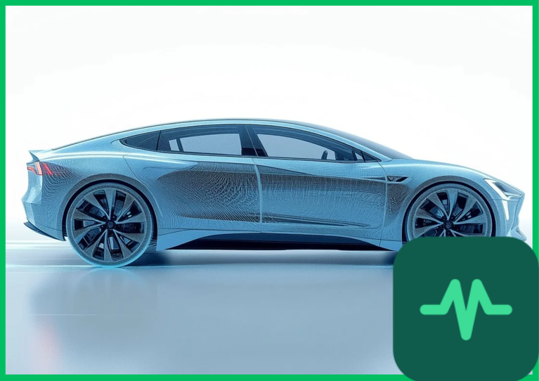
 (
 ), accounting for over 50% to 60% of total road load energy consumption during highway cruising. Unlike internal combustion engine vehicles that require massive front grille openings for high-volume radiator cooling airflow, battery-electric vehicles feature sealed front fascias and optimized exterior profiles. Minimizing the drag coefficient (
 ) extends driving range significantly without requiring costly increases in battery pack capacity.
Aerodynamic Drag Equation and Fluid Dynamics Physics
The foundational physical principle governing vehicle aerodynamics is the aerodynamic drag force ( ) equation derived from fluid dynamics:
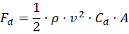
where  represents air density (
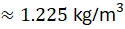 at sea level [
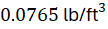 ]),
 is vehicle velocity relative to the air stream,
 is the dimensionless drag coefficient, and
 denotes the vehicle frontal cross-sectional area (
 or
 ).
Because aerodynamic drag scales quadratically with vehicle speed ( ), doubling highway speed quadruples aerodynamic drag force, demanding exponential increases in electric motor propulsion power. Total aerodynamic drag comprises two primary components: pressure drag (form drag) caused by high-pressure stagnation zones at the front fascia and low-pressure turbulent wake separation zones behind the rear trunk or tailgate, and skin friction drag resulting from boundary-layer air viscosity shearing across exterior sheet metal surfaces. Optimizing EV body geometry focuses on minimizing pressure drag by maintaining laminar boundary layer flow and preventing premature flow separation across the rear roofline and fastback profile.
Computational Fluid Dynamics (CFD) and Wind Tunnel Validation
Designing low-drag electric vehicle bodies requires advanced computational fluid dynamics (CFD) simulations coupled with physical wind tunnel testing. Automotive engineers utilize Navier-Stokes fluid flow solvers and high-performance computing clusters to model complex three-dimensional air velocity vectors, static pressure distributions, and turbulent kinetic energy fields around digital vehicle prototypes.
CFD simulations divide exterior vehicle geometry into millions of computational grid cells, calculating mass conservation and momentum equations across boundary layers. However, numerical simulations require rigorous physical validation. Automotive manufacturers test full-scale clay or composite prototypes in climatic wind tunnels equipped with rolling road dynamometers and six-component balance scales. Fine-tuning exterior surfaces—such as rounding A-pillar radii, reshaping exterior side-view mirror housings, and optimizing rear decklid spoiler lips—reduces overall drag coefficients from legacy vehicle baselines ( ) down to ultra-sleek production targets (
 ).
Technical Data Specifications of Aerodynamic Parameters
| Aerodynamic Parameter | Engineering Specification Standard |
|---|---|
Production EV Drag Coefficient ( ) |  to  aerodynamic baseline target |
Vehicle Frontal Area ( ) |  to  ( 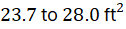 ) typical |
Air Density ( ) at Sea Level | 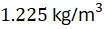 ( 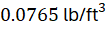 ) at  (  ) |
| Active Air Flap Actuation Speed | Deploys at  (  ) highway threshold |
| Underbody Ground Clearance Height |  to  (  ) flat enclosure |
| CFD Simulation Grid Resolution |  polyhedral finite volume cells |
| Highway Speed Power Consumption Share | 50% to 60% of total propulsion energy demand |
Active Air Flaps and Thermal Management Integration
Balancing low aerodynamic drag with high-voltage battery and power electronics thermal management requires dynamic airflow control systems. While a completely sealed front fascia delivers optimal aerodynamic drag coefficients, electric powertrains generate substantial thermal waste during high-load hill climbing, fast DC charging, and aggressive acceleration.
Modern electric vehicles integrate active grille shutters (AGS)—computer-controlled louver systems positioned behind the front bumper fascia. During low-speed city driving or high-load thermal events, active air flaps open fully to allow ambient air ingress into front-end heat exchangers, cooling the inverter, battery thermal management liquid loops, and air conditioning condensers. During high-speed highway cruising where cooling requirements diminish, active air flaps close automatically within fractions of a second, diverting high-velocity air smoothly around the exterior body contour and reducing overall drag coefficients by 0.01 to 0.03.
Underbody Airflow Smoothing and Rear Diffuser Physics
While upper body styling dominates visual aesthetics, underbody aerodynamics account for up to 30% of total vehicle drag. Raw chassis components—including suspension control arms, steering racks, exhaust tunnels (retained from internal combustion platforms), and exposed battery pack casings—create severe aerodynamic turbulence and boundary layer separation beneath the floorpan.
Electric vehicles achieve superior underbody airflow smoothing by installing flat composite or aluminum underbody shielding panels from the front bumper splitter to the rear axle. Covering rough mechanical cavities creates a laminar, high-velocity channel of air beneath the vehicle. To manage rear wake turbulence, engineers integrate tapered rear diffusers. As air accelerates beneath the flat underbody floor, the expanding geometry of the rear diffuser decelerates airflow gradually, recovering static pressure and minimizing the low-pressure suction wake behind the rear bumper, preventing trailing vortex drag.
Rolling Resistance Mechanics and Total Road Load Integration
Aerodynamic drag optimization cannot be decoupled from rolling resistance mechanics when analyzing total electric vehicle road load equations. Total tractive force ( ) required to maintain constant vehicle velocity on a level roadway is formulated mathematically as:

where  represents rolling resistance force,
 is the tire rolling resistance coefficient,
 is vehicle mass,
 is gravitational acceleration (
 [
 ]), and
 is road gradient angle.
While aerodynamic drag ( ) scales quadratically with velocity (
 ), rolling resistance (
 ) remains relatively constant across vehicle speed ranges, scaling directly with vehicle mass and tire hysteresis losses. Electric vehicles feature heavy battery packs (
 ), elevating rolling resistance forces compared to lighter vehicles. Consequently, automotive engineers pair ultra-low drag body shapes (
 ) with specialized low-rolling-resistance tires featuring high-silica tread compounds and optimized sidewall rigidity, minimizing combined road load energy losses.
The Final Take
Mastering electric vehicle aerodynamic drag coefficient optimization extends vehicle highway driving range by reducing high-speed fluid resistance forces. Citing IEA vehicle efficiency assessments and automotive engineering literature, integrating computational fluid dynamics simulations, active air flaps, and flat underbody smoothing achieves exceptional drag coefficients below 0.22. By aligning aerodynamic drag reduction with rolling resistance control, electric vehicle propulsion systems establish an indispensable foundation for maximum energy efficiency.

Comments (0)
Login to leave a comment.
No comments yet. Be the first to share your thoughts!