
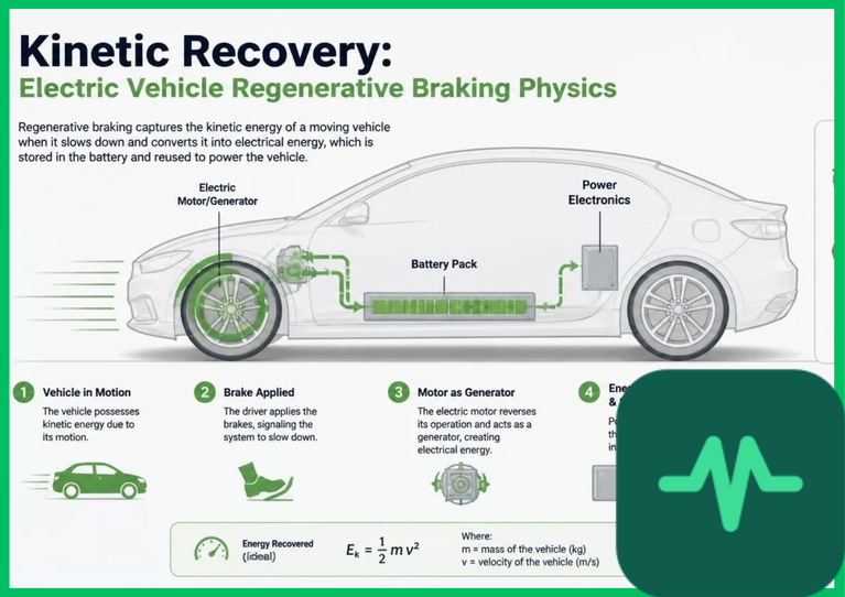
Kinetic Energy Conversion and Newtonian Deceleration Mechanics
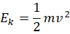
The foundational physical principle governing kinetic energy recovery is the conservation of mechanical energy and Newton's laws of motion. The kinetic energy ( ) of an electric vehicle traveling at total vehicle mass (
 ) and instantaneous linear velocity (
 ) is formulated mathematically as:
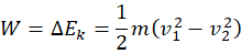
When the vehicle decelerates from initial velocity ( ) to final velocity (
 ), the mechanical work (
 ) extracted by the electric motor operating as a generator is governed by the work-energy theorem:
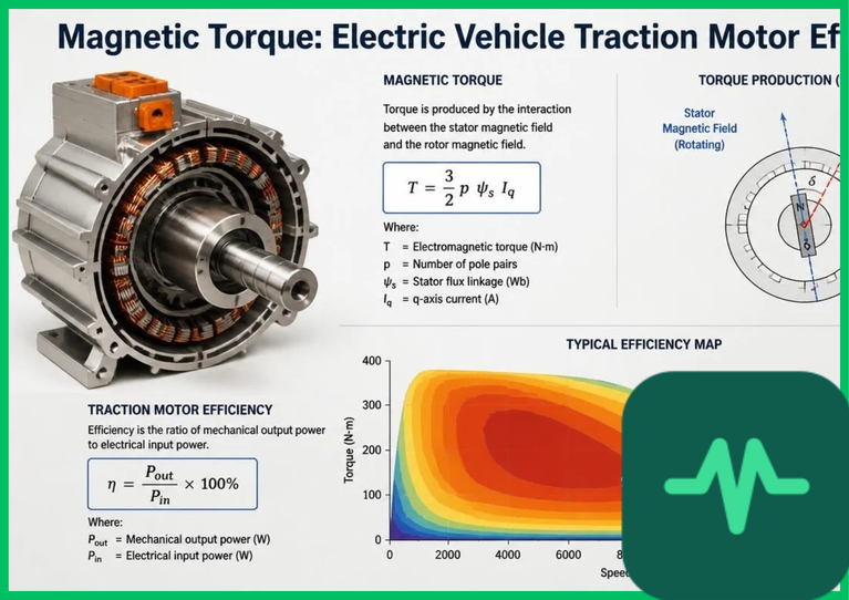
In a permanent magnet synchronous motor (PMSM) or AC induction motor, decelerating wheel rotation forces the rotor to spin at a rotational velocity exceeding the synchronous speed of the rotating magnetic field generated by the stator windings. This dynamic state induces negative slip or negative electromagnetic torque.
The rotor-stator magnetic interaction forces the electric machine to operate in generator mode, transforming vehicle kinetic energy into alternating current (AC) electrical power within the stator coils. The generated electrical power ( ) is proportional to rotational speed (
 ) and braking torque (
 ):

where  represents internal stator winding copper Joule heating losses.
Four-Quadrant Inverter Topologies and Power Electronic Efficiency
Converting variable-frequency, variable-voltage AC power generated by the decelerating traction motor back into direct current (DC) for the high-voltage traction battery requires advanced four-quadrant power electronic inverters. Standard motor inverters utilize insulated-gate bipolar transistors (IGBTs) or wide-bandgap silicon carbide (SiC) MOSFET switches controlled via space-vector pulse-width modulation (SV-PWM).
In Quadrant II (forward braking: positive rotational speed, negative electromagnetic torque) and Quadrant IV (reverse braking: negative rotational speed, positive electromagnetic torque), the power electronic inverter switches operate in synchronous rectification mode. Instead of drawing DC battery power to create rotating magnetic fields, the inverter rectifies the multi-phase AC output generated by the stator windings into regulated DC voltage ( to
 DC). High-frequency switching minimizes harmonic distortion and achieves round-power electronic conversion efficiencies exceeding 92% to 95%, ensuring minimal thermal dissipation losses across semiconductor switching junctions.
Technical Data Specifications of Regenerative Braking Parameters
| Regenerative Braking Parameter | Engineering Specification Standard |
|---|---|
| Kinetic Energy Recovery Efficiency | 15% to 30% total driving cycle energy recovery |
| Inverter Operating Quadrants | Four-quadrant operation (Motoring and Generating) |
| Power Semiconductor Switches | Silicon Carbide (SiC) MOSFET / IGBT modules |
| Maximum Regenerative Deceleration Rate |  to  deceleration ( 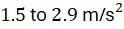 ) |
| Battery Maximum Acceptance C-Rate |  to  transient charging limit |
| Traction Motor Topologies | Permanent Magnet Synchronous Motor (PMSM) / Induction |
| Hydraulic Friction Brake Blending | Integrated electromechanical brake-by-wire coordination |
Battery Acceptance Limits and Electrochemical State-of-Charge
While high-speed deceleration generates massive electrical power spikes—frequently exceeding  to
 instantaneous power—the high-voltage traction battery pack cannot always accept 100% of the recovered energy due to electrochemical limitations. Battery acceptance current is restricted by lithium-ion intercalation kinetics, state-of-charge (SoC) thresholds, and internal cell temperatures.
When the traction battery SoC approaches 95% to 100%, or when cell core temperatures drop below  (
 ), high-rate charging induces rapid lithium plating on graphite anodes. Lithium plating causes permanent capacity degradation and creates internal short-circuit risks via microscopic dendrite formation. Battery management systems (BMS) continuously monitor cell electrochemical impedance, terminal voltage, and internal temperature telemetry. When battery acceptance thresholds are exceeded, the BMS restricts maximum regenerative braking torque, transferring excess deceleration load to friction brakes to protect cell structural integrity.
Friction Brake Blending and Hydraulic Coordination
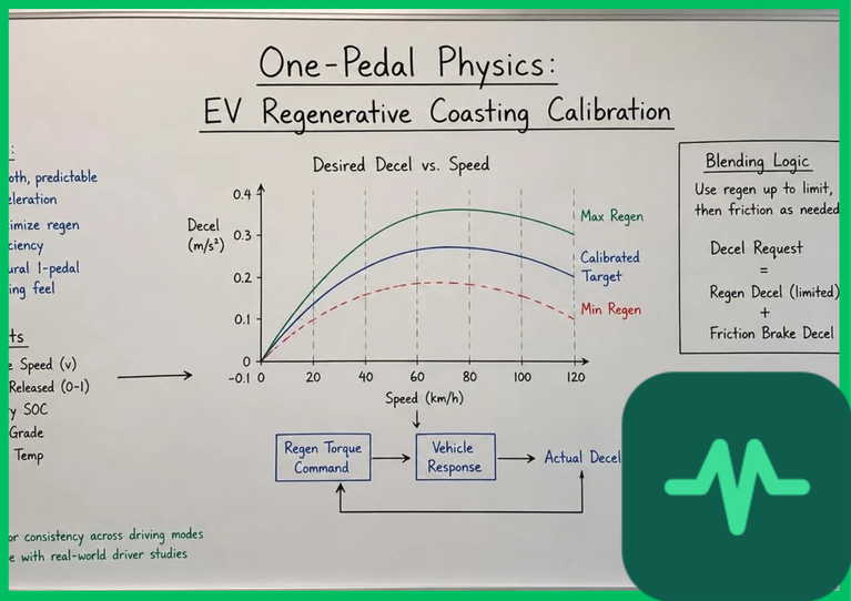
Managing the transition between regenerative electrical braking and traditional hydraulic friction brakes requires advanced brake-by-wire blending algorithms. Because regenerative braking torque depends dynamically on vehicle speed, gear ratios, and battery state-of-charge, relying solely on motor deceleration produces inconsistent deceleration rates, particularly at low speeds ( [
 ]) where electromagnetic motor torque drops to zero.
Electro-hydraulic brake (EHB) systems coordinate friction brake blending in real time. As vehicle speed decreases and motor regenerative braking capability tapers off, hydraulic actuators apply precise fluid pressure to brake calipers, maintaining a smooth, linear deceleration curve perceived by the vehicle operator. Furthermore, during anti-lock braking system (ABS) activation, electronic control units modulate regenerative torque instantaneously within milliseconds to prevent wheel lockup on low-friction road surfaces, ensuring directional stability.
The Final Take
Mastering electric vehicle regenerative braking energy recovery maximizes vehicle operating range by converting mechanical deceleration kinetics into electrical energy. Citing IEA vehicle efficiency assessments and automotive engineering literature, four-quadrant silicon carbide inverters and electro-hydraulic brake blending systems achieve energy recovery efficiencies between 15% and 30%. By balancing battery electrochemical acceptance limits with advanced power electronic switching, regenerative braking establishes an indispensable foundation for efficient electric vehicle propulsion.
Comments (0)
Login to leave a comment.
No comments yet. Be the first to share your thoughts!