
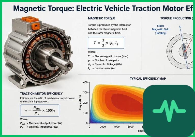
Electromagnetic Torque Equations and PMSM Physics
The foundational physical principle governing permanent magnet synchronous motor efficiency is the Lorentz force law combined with electromagnetic induction, which generates continuous rotor rotation via synchronous magnetic fields. Total electromagnetic torque ( ) developed in an interior permanent magnet synchronous motor is formulated mathematically by combining permanent magnet alignment torque and reluctance torque components:

where  represents the number of pole pairs,
 is the permanent magnet flux linkage,
 and
 denote the d-axis and q-axis stator current components, and
 and
 are the d-axis and q-axis stator inductances.
In a surface-mounted permanent magnet motor, torque generation relies almost entirely on the first term ( ), representing magnetic interaction between rotor permanent magnets and the rotating stator magnetic field. In contrast, interior permanent magnet (IPM) motors embed rare-earth magnets inside the rotor steel core, creating magnetic saliency (
 ). This magnetic asymmetry generates a secondary reluctance torque component (
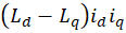 ), allowing engineers to optimize torque output while minimizing rare-earth magnet mass.
Rare-Earth Neodymium-Iron-Boron ( ) Magnets and Thermal Demagnetization
Achieving high power density and torque output requires high-energy-product permanent magnets fabricated from neodymium-iron-boron ( ) alloys.
 magnets possess exceptional residual magnetic flux density (
 ) and high intrinsic coercivity, enabling high magnetic field strengths within tight rotor dimensions.
However, a critical engineering constraint governing  permanent magnets is thermal demagnetization vulnerability. As traction motor operating temperatures rise due to high stator current densities and rotor core eddy current heating, coercive force decreases. When rotor core temperatures exceed critical thresholds (
 to
 [
 to
 ]), permanent magnets undergo irreversible thermal demagnetization, permanently degrading motor torque output.
To maintain coercivity at elevated temperatures, manufacturers alloy heavy rare-earth elements such as dysprosium ( ) or terbium (
 ) into the
 crystal lattice, or deploy grain-boundary diffusion processes. Furthermore, advanced liquid cooling jackets integrated directly into the stator housing and hollow rotor shafts maintain stator winding temperatures below
 (
 ), preventing thermal degradation.
Technical Data Specifications of Traction Motor Parameters
| Traction Motor Parameter | Engineering Specification Standard |
|---|---|
| Peak Motor Efficiency | 95% to 97% electromechanical conversion efficiency |
| Permanent Magnet Alloy Composition | Neodymium-Iron-Boron ( ) with Dysprosium |
| Rotor Maximum Thermal Operating Limit |  to  (  to  ) |
| Stator Winding Architecture | Rectangular copper hairpin conductors |
| Stator Slot Fill Factor | 70% to 75% copper packing density |
| Stator Lamination Steel Thickness |  to  silicon steel sheets |
| Maximum Rotor Rotational Velocity | 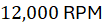 to 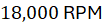 high-speed design |
Stator Winding Optimization and Hairpin Copper Conductors
Minimizing copper Joule heating losses ( ) within stator windings represents a primary focus of modern traction motor engineering. Legacy electric motors utilized round copper wire pulled manually into stator slots, resulting in low slot fill factors (50% to 55%) and substantial interstitial air void spaces that impeded thermal conduction.
Modern high-efficiency traction motors replace round wire with pre-formed, rectangular copper "hairpin" conductors inserted directly into precision-stamped stator slots. Hairpin windings achieve slot fill factors exceeding 70% to 75%, packing significantly more conductive copper mass into identical physical dimensions. Increasing copper cross-sectional area reduces stator electrical resistance ( ), lowering ohmic
 copper losses by 10% to 15%. Additionally, rectangular hairpin conductors suppress high-frequency skin effect current crowding at rotational velocities exceeding
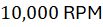 , ensuring uniform current density distribution across the conductor profile.
Core Eddy Current Losses and Electromagnetic Hysteresis
Beyond copper winding resistance, traction motor efficiency is constrained by core losses occurring within the ferromagnetic stator and rotor lamination stacks. When high-frequency alternating current ( to
 ) supplied by wide-bandgap silicon carbide (SiC) inverters magnetizes the stator iron core, energy is dissipated continuously via two primary mechanisms: hysteresis losses and eddy current losses.
Electromagnetic hysteresis losses occur as magnetic domain walls reorient continuously within the iron crystal lattice during alternating magnetic flux reversals. Hysteresis loss ( ) scales linearly with operating frequency and is governed by Steinmetz's empirical equation:

where  is the hysteresis coefficient,
 is electrical frequency,
 is peak magnetic flux density, and
 is the Steinmetz exponent (typically
 ).
Simultaneously, changing magnetic fluxes induce circulating parasitic electrical currents—known as eddy currents—within the iron core, generating internal Joule heating. To suppress eddy current losses, motor manufacturers stamp stator and rotor cores from ultra-thin silicon steel laminations ( to
 [
 ] thickness). Each lamination sheet is coated with an electrically insulating inorganic varnish layer, breaking electrical continuity across the core cross-section and restricting eddy current circulation paths, limiting core loss dissipation to less than 2% to 3% of total motor input power.
The Final Take
Mastering electric vehicle traction motor permanent magnet efficiency maximizes EV powertrain performance by uniting high-energy neodymium-iron-boron magnets with optimized hairpin stator windings. Citing IEA vehicle technology roadmaps and powertrain engineering literature, reducing core eddy current losses and maintaining strict thermal operating limits achieves electromechanical conversion efficiencies exceeding 95%. By advancing magnetic torque physics and lamination metallurgy, electric vehicle traction motors establish an indispensable foundation for high-efficiency vehicle propulsion.
Comments (0)
Login to leave a comment.
No comments yet. Be the first to share your thoughts!