Brushless DC Motor Dynamics and Electromagnetic Losses
Electric mid-drive units rely on permanent-magnet brushless direct current (BLDC) motors operating at high rotational speeds, typically ranging from  to
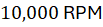 . Stator windings receive multi-phase alternating currents generated by an onboard electronic speed controller (ESC) executing field-oriented control (FOC).
Electromechanical efficiency is constrained by two primary electrical loss categories: copper losses ( resistive heating within stator windings) and core iron losses (hysteresis and eddy current losses within silicon steel laminations). Minimizing core losses requires high-permeability magnetic core sheets and optimized stator slot geometries. High-frequency pulse-width modulation (PWM) switching frequencies, ranging from
 to
 , reduce current ripple, preventing localized thermal spikes and protecting neodymium-iron-boron (
 ) permanent magnets from thermal demagnetization thresholds exceeding
 (
 ).
Planetary Gear Transmissions and Mechanical Advantage
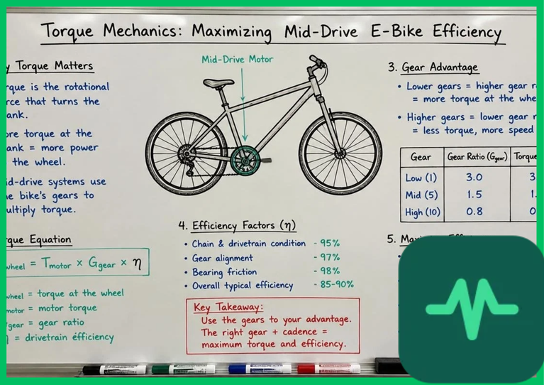
Because optimal BLDC motor efficiency occurs at high angular velocities and low torque, mid-drive architectures incorporate internal planetary gear transmissions to step down motor speed while multiplying output torque. An epicyclic gear train comprises a central sun gear, multiple planet gears mounted on a rotating carrier, and an outer ring gear.
This internal gear reduction—typically operating at ratios between 20:1 and 50:1—converts high motor speeds into high-torque output applied directly to the chainring. Mechanical efficiency of high-precision helical planetary gear sets exceeds 95%, governed by tooth-mesh friction coefficients and lubricant shear resistance. By coupling motor torque directly to the crank axle, mid-drive systems allow the rider's cadence to leverage the bicycle's mechanical gear cassette, maintaining motor operation within its peak efficiency island (85% to 92% efficiency) across varying road gradients and vehicle speeds.
Technical Data Specifications of Mid-Drive Powertrains
| Technical Parameter | Engineering Specification Range |
|---|---|
| Motor Rotational Speed |  to 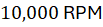 |
| Planetary Reduction Ratio | 20:1 to 50:1 epicyclic gear reduction |
| Peak Torque Output |  to  (  to  ) |
| Inverter Switching Frequency |  to  pulse-width modulation |
| Operating Thermal Limit | Up to  (  ) stator winding temperature |
| Torque Sensor Latency |  response time |
Torque Sensing Bottom Bracket Mechanics
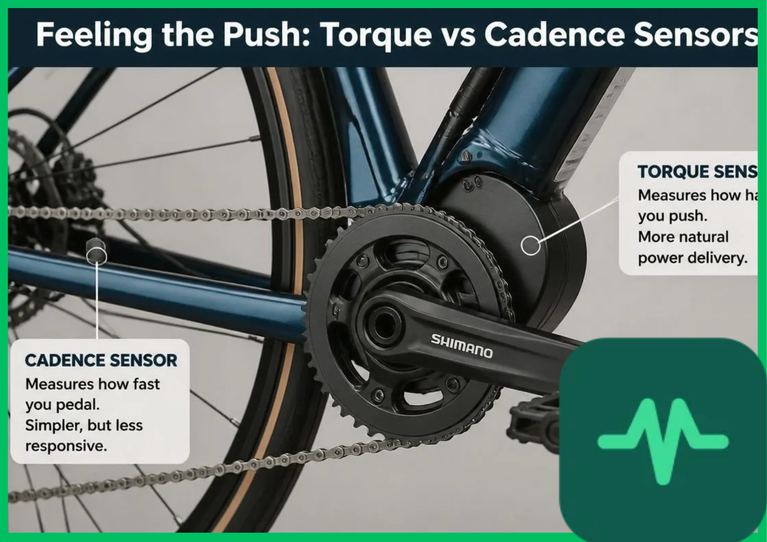
Precise torque delivery relies on instantaneous rider input detection via a torque sensing bottom bracket. Unlike basic cadence-only systems that simply activate motor power upon crank rotation, torque sensors measure the elastic torsional deformation of the bottom bracket axle under rider pedaling forces.
Advanced systems utilize magnetostrictive sensors or semiconductor strain gauges bonded to the internal axle shaft. When a rider exerts pedal force—reaching peak values of  to
 (
 to
 ) during aggressive acceleration—the axle experiences micro-torsion. Magnetostrictive sensors detect permeability changes in the ferromagnetic axle material caused by this mechanical stress, translating physical deflection into an analog voltage signal within milliseconds (
 response latency). This instantaneous feedback loop enables proportional motor torque amplification, matching human pedaling effort seamlessly without perceptual lag.
Cadence Sensor Calibration and Motor Controller Algorithms
Complementing torque detection, cadence sensor calibration tracks crank rotational velocity to refine motor output. Optical encoders or quadrature Hall-effect sensors embedded within the bottom bracket housing monitor magnetic ring rotation, measuring pedal cadence from  to
 .
Motor controllers process torque and cadence data simultaneously through digital signal processors (DSPs). Advanced field-oriented control algorithms decouple stator current into flux-producing and torque-producing components, maximizing instantaneous torque per Ampere (MTPA). This algorithmic optimization prevents current surges during stall conditions, reducing thermal stress on the controller metal-oxide-semiconductor field-effect transistors (MOSFETs) and battery management system (BMS).
Thermal Management and Copper Losses ( )
Continuous high-torque operation generates substantial internal thermal energy, threatening permanent magnet degradation and insulation breakdown. Copper losses scale exponentially with stator current ( ). When operating under heavy loads on steep inclines, internal stator temperatures can rise from ambient conditions up to
 (
 ).
Effective thermal management requires integrating thermally conductive potting compounds, aluminum alloy motor casings with external cooling fins, and internal negative temperature coefficient (NTC) thermistors. These thermistors provide real-time thermal telemetry to the electronic speed controller, triggering automated current derating when internal temperatures approach critical thresholds. Derating protects stator wire enamel insulation and preserves permanent magnet coercivity, ensuring long-term drivetrain reliability.


Comments (0)
Login to leave a comment.
No comments yet. Be the first to share your thoughts!