
Strain Gauge Deflection Physics and Magnetostrictive Sensing
The foundational electromechanical principle governing e-bike torque sensing is the conversion of mechanical elastic deformation into precise electrical analog signals via strain gauge deflection physics or magnetostrictive material property shifts. When a cyclist applies downward force to the pedal crank, the bottom bracket spindle, chainring spider, or axle experiences microscopic torsional or bending deflection.
In resistance-based strain gauge configurations, ultra-thin metallic foil strain gauges are bonded directly to the structural steel or aluminum spindle. As torque ( ) twists the spindle by fractions of a millimeter, the attached strain gauges elongate or compress. This physical deformation alters the electrical resistance (
 ) of the strain gauge element in direct proportion to the applied mechanical strain (
 ).
Engineers configure these strain gauges into a Wheatstone bridge circuit to measure minute resistance changes while canceling out thermal expansion errors. The output voltage ( ) of the Wheatstone bridge is formulated mathematically as:

where  is excitation voltage and
 through
 represent bridge resistor values modified by mechanical deflection. Alternatively, magnetostrictive torque sensors measure magnetic permeability changes in ferromagnetic spindle shafts under mechanical stress, eliminating physical electrical contacts and delivering high mechanical durability.
Pedal Cadence Harmonics and Motor Controller Response Time
Processing raw torque sensor signals requires sophisticated signal filtering to isolate human biomechanical pedal cadence harmonics from mechanical drivetrain vibrations. Human pedaling operates within a fundamental frequency range of  (
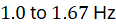 ). However, foot strikes, chain vibration, and road surface impacts introduce high-frequency noise harmonics that can corrupt torque measurements if unmanaged.
Advanced motor controllers sample analog torque and cadence signals at frequencies ranging from  to
 , utilizing digital low-pass filters and Fast Fourier Transform (FFT) algorithms to strip mechanical noise while preserving true rider input dynamics. Minimizing motor controller response time is critical; total system latency—measured from the instant the rider initiates pedal pressure to the moment the brushless motor delivers proportional torque—must remain under 20 milliseconds to eliminate perceived drivetrain lag and ensure seamless electromechanical synchronization.
Technical Data Specifications of E-Bike Torque Sensors
| E-Bike Torque Sensor Parameter | Engineering & Drivetrain Specification Standard |
|---|---|
| Torque Measurement Range |  (  ) active load |
| Sensor Sampling Frequency |  to  digital microcontroller polling |
| Total System Response Latency |  pedal-to-motor activation |
| Strain Gauge Bridge Configuration | Full Wheatstone bridge with thermal compensation |
| Cadence Resolution Accuracy |  optical or Hall-effect encoder tracking |
| Operating Voltage Excitation |  DC regulated microcontroller supply |
| System Power Assist Ratio | 50% to 350% proportional torque amplification |
Battery Energy Discharge Optimization and Ampere-Hour Efficiency
A primary operational advantage of torque-sensing drivetrains over cadence-only systems is advanced battery energy discharge optimization. Cadence sensors deliver flat, unmodulated motor power whenever the cranks spin, irrespective of whether the rider is climbing a steep incline or coasting lightly on flat terrain. This unregulated power delivery forces the lithium-ion battery pack to experience high C-rate current spikes, accelerating internal Joule heating ( ) and reducing total ampere-hour capacity extraction.
Torque-sensing systems couple motor assistance linearly to rider effort, ensuring that electrical energy from the lithium-ion battery ( to
 nominal bus voltage) is discharged only when mechanical work is demanded. By smoothing current draw profiles and eliminating unnecessary high-current bursts, torque-controlled powertrains reduce internal battery thermal dissipation losses by 15% to 25%. According to academic electric mobility evaluations, this precise energy management extends real-world e-bike riding range by 20% to 30% on equivalent battery capacities.
Closed-Loop Field-Oriented Control (FOC) and Inverter Efficiency
Translating torque sensor signals into mechanical propulsion requires high-efficiency motor control electronics. Modern e-bike hub and mid-drive motors utilize brushless DC (BLDC) or permanent magnet synchronous motors (PMSMs) governed by closed-loop field-oriented control (FOC) algorithms executed via microcontrollers.
Field-oriented control decouples motor stator current into magnetic flux-producing ( -axis) and torque-producing (
 -axis) components. By maintaining precise orthogonal alignment between the rotor permanent magnet flux and the stator magnetic field, FOC maximizes electromechanical conversion efficiency across wide rotational speed ranges (
 to
 crank speed, or up to
 for direct-drive hub motors).
Wide-bandgap metal-oxide-semiconductor field-effect transistors (MOSFETs) operating via space-vector pulse-width modulation (SV-PWM) achieve inverter conversion efficiencies exceeding 95% to 98%. This high electronic efficiency ensures that electrical energy harvested from the battery is converted into mechanical torque with minimal thermal waste, preventing controller overheating during continuous high-load hill climbing.
Comments (0)
Login to leave a comment.
No comments yet. Be the first to share your thoughts!