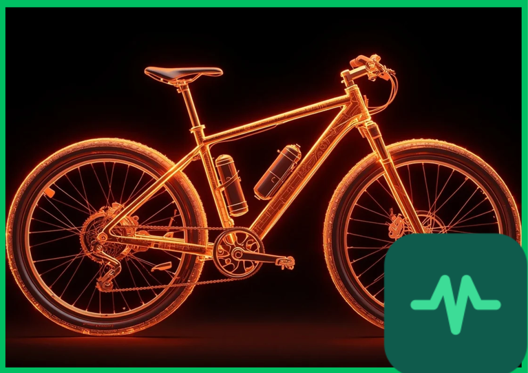
Hub Motor Architecture and Direct-Drive Thermal Constraints
Hub motors position the electromagnetic stator and permanent-magnet rotor directly inside the wheel hub, operating either as direct-drive configurations or via internal planetary gear reduction. In direct-drive hub motors, the stator is rigidly bolted to the stationary axle, surrounded by an enclosed aluminum shell rotating with the wheel. Because the motor sits within a sealed environment isolated from external airflow, heat rejection relies entirely on conductive transfer through the aluminum casing and natural convection across the outer rim surface.
Under high-torque, low-speed operating conditions—such as ascending a steep 10% gradient slope at reduced wheel velocities—back-electromotive force (back-EMF) drops, forcing the motor controller to supply high electrical current to maintain torque. This elevated current surges  ohmic losses inside the copper stator windings, while the low rotational speed minimizes forced convective cooling. Consequently, direct-drive hub motors frequently experience rapid thermal saturation, reaching internal stator temperatures exceeding
 to
 (
 to
 ) within minutes of sustained high-load operation.
Mid-Drive Powertrain Engineering and Gear Reduction
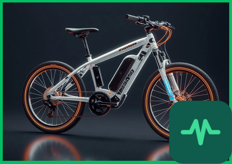
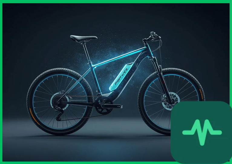
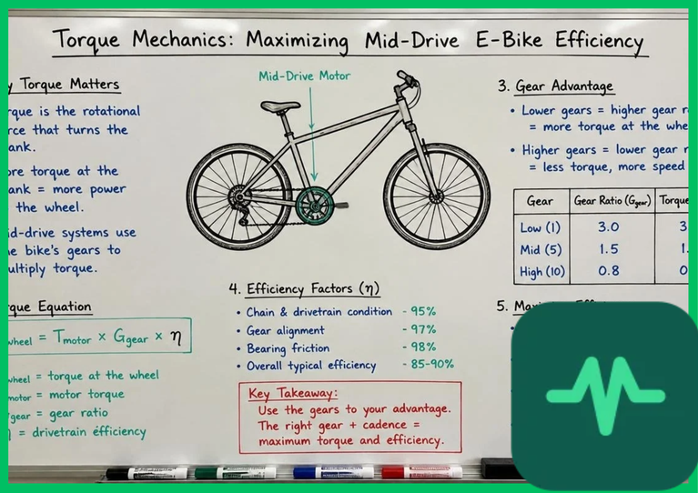
Mid-drive motor architectures mount the electric propulsion unit at the central bottom bracket shell, utilizing the bicycle's existing mechanical chain, cassette, and derailleur gear train to transmit rotational torque to the rear wheel. This structural configuration introduces a mechanical gear reduction ratio between the motor rotor and the driven wheel. By leveraging multi-speed bicycle transmissions, a mid-drive motor operates at higher rotational speeds (RPM) and lower torque levels to deliver identical wheel traction compared to a direct-drive hub motor.
Operating at higher angular velocities enables smaller motor mass, higher power density, and more efficient electromagnetic operation closer to peak efficiency RPM islands. Furthermore, because mid-drive motors integrate directly into the frame structure, manufacturers incorporate external finned aluminum heat sinks and thermal conductive potting compounds that transfer stator heat directly into the bicycle frame or ambient air via enhanced forced convection during forward motion.
Ohmic Resistance Heating and Thermal Demagnetization
The primary thermodynamic constraint governing electric motor thermal limits is ohmic resistance heating ( ) within stator copper windings and thermal degradation of permanent magnets. The rate of internal heat generation (
 ) is quantified by the electrical equation:
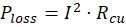
where  represents phase current in Amperes (
 ) and
 denotes the temperature-dependent electrical resistance of the copper windings. As winding temperature rises, copper resistivity increases linearly, compounding thermal generation rates in a positive feedback loop known as thermal runaway.
When internal stator temperatures surpass the thermal insulation class rating (typically Class F [ (
 )] or Class H [
 (
 )]), varnish insulation breaks down, causing short-circuits between adjacent winding turns. Simultaneously, permanent-magnet rotor assemblies utilizing neodymium-iron-boron (
 ) magnets suffer irreversible magnetic demagnetization if exposed to temperatures exceeding their Curie threshold (typically
 to
 [
 to
 ] for standard grades, or up to
 [
 ] for high-coercivity grades), permanently reducing motor torque constant (
 ) and operational efficiency.
Technical Data Specifications of E-Bike Motor Thermal Parameters
| Thermal & Electromechanical Parameter | Direct-Drive Hub Motor | Mid-Drive Powertrain System |
|---|---|---|
| Mechanical Transmission Ratio | 1:1 direct wheel coupling | Multi-speed chain and cassette reduction |
| Stator Thermal Dissipation Pathway | Sealed air gap to rotating aluminum shell | Direct frame conduction and external heat sinks |
| Maximum Continuous Operating Temp |  to  (  to  ) |  to  (  to  ) |
| Winding Insulation Temperature Class | Class B ( [  ]) to Class F (  [  ]) | Class H ( [  ]) high-temperature rating |
| Thermal Saturation Time (Hill Climb) |  to  under high load |  to  under high load |
| Cooling Enhancement Technology | Optional ferrofluid gap injection | Integrated thermal potting and finned housing |
| Continuous Power-to-Weight Ratio | Lower thermal-limited continuous output | Higher continuous output via gear multiplication |
Forced Convection, Ferrofluids, and Thermal Interface Materials
Advanced thermal engineering strategies mitigate overheating in both motor architectures. Geared hub motors mitigate thermal bottlenecks by incorporating internal planetary gear sets that allow the internal motor core to spin at higher speeds relative to the wheel, reducing continuous winding current requirements. To enhance thermal conductivity within sealed direct-drive hub motors, manufacturers inject specialized magnetic ferrofluids into the air gap between the stator and rotor. Ferrofluids bridge the air gap with a colloidal suspension of magnetic nanoparticles in a synthetic carrier fluid, reducing thermal resistance by 30% to 50% and transferring heat rapidly from the inner stator to the outer aluminum housing via magnetic attraction fields.
Mid-drive systems deploy internal temperature sensors (negative temperature coefficient thermistors) coupled with motor controller firmware that automatically throttles phase current when stator temperatures exceed safety limits. This active thermal foldback prevents winding insulation breakdown during sustained high-load climbing operations.
The Final Take
Mastering e-bike mid-drive vs hub motor thermal management highlights the critical role of mechanical gear reduction and thermal dissipation pathways in electric mobility reliability. Citing International Energy Agency transport assessments and academic electrical engineering literature, mid-drive powertrains leverage multi-speed transmissions to operate at higher efficiencies and lower continuous winding currents, whereas direct-drive hub motors require advanced ferrofluid cooling or active current throttling to prevent thermal saturation. By understanding ohmic resistance heating and magnetic Curie limits, engineers optimize continuous power delivery and thermal durability across micro-mobility platforms.
Comments (0)
Login to leave a comment.
No comments yet. Be the first to share your thoughts!