
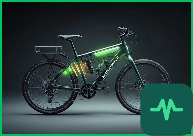
Brushless Motor Regeneration and Four-Quadrant Inverter Physics
The foundational electromechanical principle governing e-bike regeneration is the transition of a permanent magnet synchronous motor (PMSM) or brushless DC (BLDC) motor from a motoring state into a generative braking mode. During normal propulsion, electrical energy from the battery creates a rotating magnetic field in the stator that drags the permanent magnet rotor forward. During regenerative braking, the physical momentum of the bicycle forces the rotor to spin faster than the rotating magnetic field generated by the motor controller, reversing the torque vector and turning the electric motor into an electrical generator.
This transition requires four-quadrant inverter control. Standard motor controllers operate primarily in Quadrant I (forward motoring). Regenerative braking shifts operation into Quadrant II (forward braking), where mechanical kinetic energy drives negative torque production while generating positive electrical current flow back toward the power source.
As the rotor spins within the stator windings, it induces a back-electromotive force (back-EMF,  ), formulated mathematically as:

where  represents the motor back-EMF constant (
 ) and
 is the rotational angular velocity of the rotor (
 ). When the magnitude of the generated back-EMF exceeds the nominal DC bus voltage of the battery pack, current flows backward through wide-bandgap metal-oxide-semiconductor field-effect transistors (MOSFETs) into the energy storage system, governed by high-frequency pulse-width modulation (PWM) boosting algorithms.
Braking Torque Modulation and Electronic Control Units (ECUs)
Controlling regenerative deceleration requires precise electronic braking torque modulation to prevent sudden rear-wheel lockup and maintain vehicle stability. If a regenerative braking controller applies instantaneous, unmodulated reverse torque to the hub or mid-drive motor, the abrupt deceleration rate can exceed the friction coefficient of the tire-road interface, inducing dangerous skidding—particularly on wet or loose asphalt surfaces.
Advanced e-bike electronic control units (ECUs) sample brake lever displacement sensors or tension strain gauges at frequencies exceeding  . When the rider engages the brake lever, the ECU initiates a smooth ramp-up of the PWM duty cycle, controlling the phase currents delivered back to the battery busbar. This progressive braking torque modulation ensures that regenerative deceleration blends seamlessly with traditional hydraulic or mechanical disc brakes, prioritizing rider safety while maximizing total energy capture during long descents or urban intersection stops.
Technical Data Specifications of Regenerative Braking Parameters
| Regenerative Braking Parameter | Engineering & Drivetrain Specification Standard |
|---|---|
| Controller Sampling Frequency |  microcontroller digital polling rate |
| Regenerative Torque Range |  (  ) adjustable braking force |
| Power Electronics Inverter Efficiency | 92% to 95% DC-to-DC boost conversion efficiency |
| Battery Maximum Charge Acceptance C-Rate |  to  safe electrochemical threshold |
| Nominal System Bus Voltage |  to  DC lithium-ion architecture |
| Net Urban Riding Range Extension | 10% to 18% energy recovery improvement |
| Back-EMF Voltage Generation Limit | Exceeding DC bus voltage threshold via boost PWM |
Battery Charge Acceptance Limits and Electrochemical Kinetics
A primary engineering constraint limiting e-bike regenerative braking efficiency is the strict electrochemical charge acceptance limit of high-density lithium-ion battery cells. While capturing 100% of the kinetic energy released during a rapid, high-deceleration stop is physically possible from a motor-generator perspective, forcing massive electrical current into the battery pack over a 2-second stop exceeds safe C-rate acceptance thresholds.
Standard lithium-ion battery cells utilizing nickel-manganese-cobalt (NMC) or lithium iron phosphate ( ) chemistries exhibit finite ionic diffusion rates through liquid organic carbonate electrolytes and solid electrolyte interphase (SEI) layers. Attempting to force high current pulses into the battery during rapid regenerative braking elevates internal cell resistance, inducing severe Joule heating (
 ). More critically, excessive charging currents at low ambient temperatures push the anode potential below the lithium reduction potential, causing irreversible metallic lithium plating onto the graphite anode surface. Lithium plating leads to dendritic micro-punctures of the polymer separator, triggering internal short circuits and permanent capacity degradation.
To protect battery health, advanced battery management systems (BMS) and motor controllers enforce strict charge current ceilings (limiting regeneration currents to  to
 ). When braking energy exceeds battery acceptance limits, excess energy is safely dissipated as thermal waste via onboard ceramic brake resistors or absorbed by high-capacity ultracapacitor hybrid buffers.
Energy Conversion Efficiency and Net Range Extension Realities
Evaluating the real-world utility of e-bike kinetic energy recovery requires analyzing total conversion chain efficiency and net range extension metrics. Energy recovery efficiency is the product of multiple sequential conversion steps: mechanical drivetrain transmission efficiency, generator electromechanical conversion efficiency, power electronics DC-DC boost efficiency, and electrochemical battery charging efficiency.
Under optimized operating conditions, the combined round-trip efficiency of an e-bike regenerative braking system ranges from 60% to 75%. When factored across typical urban stop-and-go riding cycles characterized by frequent accelerations and decelerations, regenerative braking yields a net range extension of 10% to 18%. While lower than heavy electric vehicles due to smaller vehicle mass and lower kinetic inertia, regenerative braking significantly reduces mechanical brake pad wear, lowers maintenance expenditures, and extends thermal stability across extended descents.
Comments (0)
Login to leave a comment.
No comments yet. Be the first to share your thoughts!