
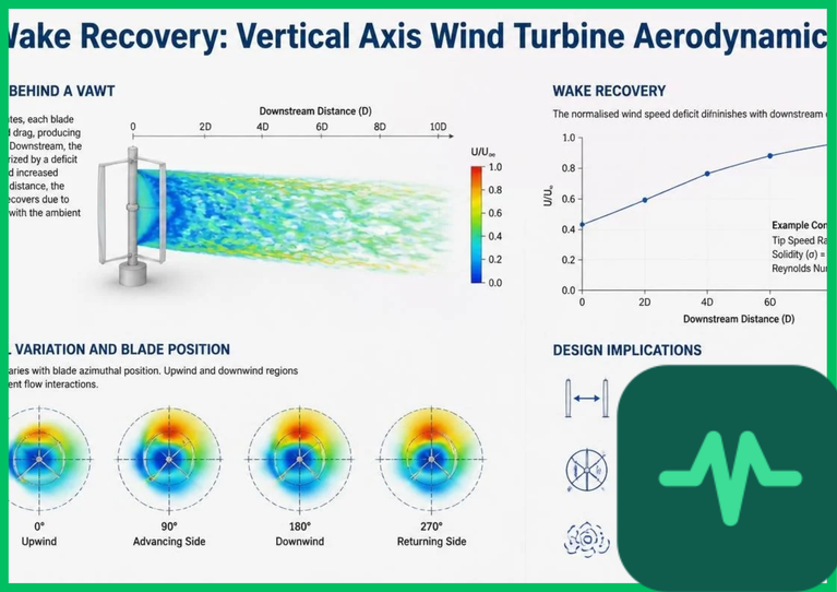
Aerodynamic Wake Structure and Downward Momentum Transfer
The wake recovery mechanics of a vertical axis wind turbine differ fundamentally from those of a horizontal-axis rotor because the swept rotor plane is oriented vertically rather than perpendicular to the ground boundary layer. As wind passes a Darrieus or helical VAWT, advancing and retreating blades sweep through continuously varying angles of attack ( ), producing asymmetric lateral pressure gradients and shedding spanwise vortices along vertical blade tips and struts.
In counter-rotating VAWT pairs—where adjacent turbines spin in opposite directions—the induced lateral velocity components reinforce each other on the inner channel between rotors, accelerating local flow velocity and drawing high-energy air from above the canopy into the wake deficit. Research in turbulent boundary-layer aerodynamics indicates that vertical momentum entrainment in VAWT clusters can restore mean velocity deficits faster than in isolated horizontal-axis wakes, enabling downwind array spacing density configurations spaced closer to 4 to 6 rotor diameters without severe power penalties.
Dynamic Stall Vortex Shedding and Lift Generation
Lift-driven vertical axis wind turbines operate across continuously shifting relative inflow velocities and angles of attack as blades travel around the azimuth. During high tip-speed-ratio operation or gust transients, local angles of attack can exceed the static stall angle ( ), triggering dynamic stall vortex shedding along the airfoil suction surface.
As the angle of attack increases rapidly, a coherent dynamic stall vortex forms near the leading edge, convects chordwise along the upper airfoil surface, and sheds into the wake. This transient vortex temporarily elevates lift coefficients above static airfoil limits before stall breakdown occurs, producing cyclic torque ripples and adding small-scale turbulent mixing to the near-wake region. High-frequency small-scale eddies enhance turbulent diffusivity, mixing outer high-speed boundary-layer air into the decelerated wake core more rapidly than large-scale periodic shedding alone.
Technical Data Specifications of VAWT Wake and Aerodynamics
| VAWT Aerodynamic Parameter | Engineering & Fluid Dynamics Specification Standard |
|---|---|
Nominal Tip-Speed Ratio ( ) |  (lift-driven Darrieus / helical rotors) |
| Downwind Array Spacing Density |  rotor diameter separation in clusters |
| Operating Wind Speed Envelope |  (  ) |
| Rotor Rated Power Class | 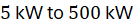 (  ) distributed/array |
| Ambient Operating Temperature | 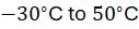 ( 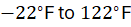 ) structural range |
| Dynamic Stall Angle Threshold | Exceeds  static stall during high loading |
Peak Power Coefficient ( ) | 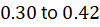 for optimized airfoil profiles |
Magnus Effect Lift Generation and Blade Pitch Modulation
While symmetrical or cambered airfoils generate aerodynamic lift through circulation and pressure differentials across curved surfaces, auxiliary rotating cylinders or Flettner-type elements exploit Magnus effect lift generation when spun within a cross-flow wind stream. Spinning cylinders deflect boundary-layer streamlines asymmetrically, creating a pressure drop on the advancing side and a pressure rise on the retreating side, though parasitic rotational drag and mechanical complexity limit standalone adoption compared to sculpted hydro- or aerodynamic blades.
On lift-type VAWTs, active or passive blade pitch modulation adjusts each blade's pitch angle ( ) around its azimuthal trajectory (
 ). Modulating blade pitch keeps effective angles of attack near optimal lift-to-drag ratios through the upwind pass while reducing negative torque and drag on the downwind pass. Controlled pitch schedules also moderate wake velocity deficits behind individual rotors, lowering downstream turbulence intensity and preventing excessive structural fatigue on adjacent array units.
Array Spacing Density and Boundary-Layer Coupling
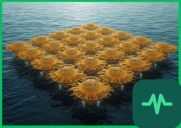
Increasing power density per unit of land or marine surface area requires balancing wake recovery rates against blockage and interference between neighboring turbines. Packing VAWTs too closely restricts inflow mass flux through the array canopy, elevating local wind speeds around the outer perimeter while starving interior rows. Conversely, spacing turbines too far apart wastes spatial capacity and raises balance-of-plant cabling or structural costs.
Computational fluid dynamics (CFD) large-eddy simulations and wind-tunnel experiments show that staggered VAWT layouts with coordinated rotational directions optimize velocity recovery downstream of leading rows. By pairing vertical momentum entrainment with moderate tip-speed ratios ( ), array designers can increase spatial power density per square meter or acre in space-constrained coastal, industrial, or multi-unit wind installations while preserving aerodynamic efficiency.

Comments (0)
Login to leave a comment.
No comments yet. Be the first to share your thoughts!