 (
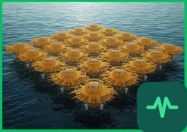
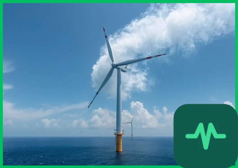
 ) requires transitioning from fixed-bottom foundations to floating platforms. These floating systems—comprising semi-submersibles, spar buoys, and tension-leg platforms (TLPs)—rely entirely on complex subsea mooring networks to restrict excessive translational and rotational displacement. Maintaining structural integrity under extreme oceanographic conditions demands rigorous mathematical modeling of catenary tension lines, hydrodynamic added mass coefficients, fairlead motion transfer, and subsea anchor holding capacity.
Catenary and Taut Mooring Configurations
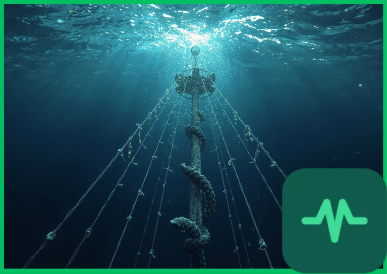
The station-keeping performance of floating wind platforms depends fundamentally on the geometric configuration and material composition of the mooring lines. Industry standards deploy two primary structural typologies: catenary mooring systems and taut or tensioned-leg mooring systems.
Catenary mooring systems utilize heavy steel chains or wire ropes deployed in a sagging curve configuration where a significant portion of the lower line rests horizontally upon the seabed. The restoring stiffness of a catenary line is derived primarily from the gravitational weight of the lifted chain segment rather than material elasticity. As hydrodynamic wave and wind forces displace the floating platform horizontally, the lifted length of the chain increases, generating a progressive restoring force. Catenary systems offer high compliance and cost-effective installation in water depths ranging from  to
 (
 ).
Conversely, taut mooring systems maintain continuous high-tension profiles using synthetic fiber ropes (such as polyester or aramid) or vertical steel tendons anchored firmly to the seabed without resting on the ocean floor. Taut systems rely on axial elastic elongation to generate restoring forces, significantly reducing the required seabed footprint while tightly restricting vertical platform motions such as heave, pitch, and roll.
Hydrodynamic Wave Loading and Morison Equation Mechanics
Subsea mooring lines are subjected to continuous hydrodynamic loading induced by orbital wave particle velocities, ocean currents, and platform fairlead motions. Calculating total hydrodynamic forces ( ) acting on submerged mooring segments requires applying modified Morison equations that account for fluid inertia, quadratic drag, and added mass:

where  denotes seawater density,
 represents the cross-sectional area of the unstretched cable,
 is the added mass coefficient,
 is fluid acceleration,
 is the normal drag coefficient,
 represents the relative velocity vector between the cable and the fluid, and
 is the wet weight per unit length.
As surface waves propagate across the mooring spread, wave-induced particle kinematics generate fluctuating hydrodynamic lift and drag forces along every submerged node. These distributed loads compound platform fairlead tension variations, increasing fatigue damage accumulation rates by 5% to 7% during severe storm sea states compared to static pretension estimations.
Technical Data Specifications of Mooring System Parameters
| Mooring & Hydrodynamic Parameter | Engineering Specification Standard |
|---|---|
| Typical Water Depth Operating Window |  to  ( 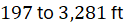 ) |
| Catenary Line Material Composition | Studless grade R3/R4 heavy steel chain |
Taut Line Axial Stiffness ( ) |  to  elastic rigidity |
Normal Drag Coefficient ( ) |  to  (cylindrical chain profile) |
Added Mass Coefficient ( ) |  to  hydrodynamic displacement factor |
| Maximum Fairlead Tension Load |  to  peak operational limit |
| Design Fatigue Life Threshold |  continuous cyclic loading |
Finite Element Modeling and Dynamic Tension Amplification
Accurately predicting mooring line behavior requires advanced numerical simulation coupling aerodynamic rotor loads, hydrodynamic wave diffraction, and non-linear finite element structural analysis. Because mooring lines undergo large three-dimensional deflections and axial straining, structural dynamics are formulated using co-rotational finite element models that solve equations of motion for multi-segmented elastic rods:
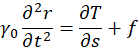
where  defines the spatial position vector along the cable length coordinate
 , and
 represents the internal axial tension force vector governed by linear elastic strain (
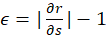 ) and material stiffness (
 ).
Dynamic amplification occurs when natural frequencies of the floating platform-mooring system coincide with wave excitation frequencies, producing snap loads or slack-line phenomena. When a catenary line goes temporarily slack due to upward platform heave, subsequent re-tensioning generates severe shock loads that exceed nominal operating tension by factors of two to three, accelerating micro-crack propagation and mechanical fatigue failure at fairlead attachment points.
Subsea Anchor Stability and Geotechnical Interaction
Securing floating offshore wind turbines against extreme environmental overturning moments requires matching subsea anchor designs to local seabed geotechnical conditions. Common anchor technologies include:
- Drag-Embedment Anchors (DEAs): Cost-effective plates dragged into soft clay or sandy seabeds, relying on horizontal soil resistance to sustain multi-directional catenary uplift loads.
- Suction Caissons (Piles): Large-diameter steel cylinders penetrated into the seabed via internal pump-induced negative pressure, providing high vertical and lateral holding capacity for taut mooring systems.
- Driven Piles and Vertically Loaded Anchors (VLAs): High-integrity structural steel piles capable of withstanding heavy vertical uplift forces typical of tension-leg platforms.
Geotechnical design standards mandate comprehensive pull-out capacity modeling under cyclic loading conditions, ensuring that subsea anchors maintain structural stability across multi-decade operational lifespans without progressive soil degradation or pull-out failure.
The Final Take
Mastering floating offshore wind turbine mooring line dynamics secures the structural reliability and commercial viability of deep-water renewable energy expansion. Citing International Energy Agency offshore assessments and marine engineering research, rigorous modeling of catenary compliance, hydrodynamic Morison forces, and non-linear finite element tension responses prevents fatigue failure under harsh wave regimes. By optimizing subsea anchor geotechnics and line configurations, floating wind systems establish an indispensable technical foundation for global marine decarbonization.
Comments (0)
Login to leave a comment.
No comments yet. Be the first to share your thoughts!