 to
 (
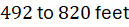 ), where wind speeds are constrained by surface friction and boundary layer shear. In contrast, airborne wind energy systems (AWES) access high-altitude winds ranging from
 to
 (
 ), where wind power density increases exponentially due to higher velocity cubed relationships (
 ). Harvesting this high-altitude kinetic energy without requiring massive concrete gravity foundations or heavy steel towers requires flying tethered aircraft along high-speed crosswind looping trajectories.
Atmospheric Boundary Layer Shear and Power Density Physics
The fundamental thermodynamic rationale driving airborne wind energy is the vertical wind shear profile of the atmospheric boundary layer. Wind velocity ( ) increases non-linearly with altitude (
 ), governed by the Hellmann atmospheric power-law equation:
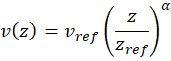
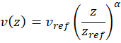
where  is the reference wind speed at reference height
 (typically
 [
 ]), and
 represents the Hellmann roughness exponent, ranging from
 over open ocean to
 over rugged terrestrial terrain.
Because kinetic wind power density scales cubically with wind velocity, elevating a harvesting device from  to
 (
 ) exposes the airfoil to wind speeds that are 50% to 100% higher, translating to a 3-to-8-fold increase in available power density. Capturing this high-altitude resource eliminates the massive structural bending moments experienced by traditional cantilevered wind turbine towers, replacing rigid steel masts with flexible, high-tensile composite tethers.
Crosswind Flight Dynamics and Apparent Wind Amplification
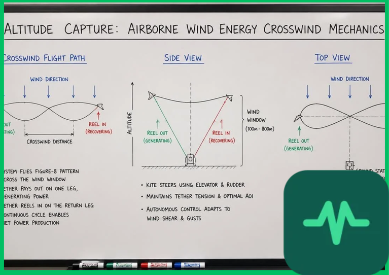
Airborne wind energy systems maximize power extraction by flying crosswind trajectories—such as figure-eight or circular looping patterns—perpendicular to the prevailing atmospheric wind vector. Flying crosswind amplifies the relative airspeed experienced by the aircraft wings far beyond the ambient wind speed, a phenomenon governed by aerodynamic lift-to-drag ratios ( ).
As the tethered aircraft banks and sweeps across the sky at high crosswind velocities ( ), the apparent wind speed (
 ) vector is calculated by combining the ambient wind velocity (
 ) with the aircraft flight velocity vector:


High-performance rigid-wing aircraft or flexible kites achieve aerodynamic lift-to-drag ratios ranging from  to
 . This high
 ratio enables crosswind flight velocities that reach 5 to 10 times the ambient wind speed (
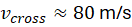 to
 [
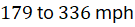 ] in a
 ambient wind). Because aerodynamic power scales with the cube of apparent wind speed (
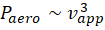 ), crosswind flight generates massive mechanical traction force along the tether, multiplying power output output per unit of aircraft mass by an order of magnitude.
Ground-Generation and On-Board Generation Operational Modes
Airborne wind energy systems operate via two distinct electrical conversion topologies: ground-generation (often termed "pumped" or "fly-gen" ground systems) and on-board generation (fly-gen aircraft).
- Ground-Generation (Pumping Mode): The tethered aircraft flies aggressive crosswind figure-eight loops, pulling against a high-tensile dielectric tether wound around a ground-based winch drum coupled to an electrical generator. The drum unwinds under high mechanical tension (reel-out phase), driving the generator to produce electrical power. Once the tether reaches maximum payout length (typically
 to
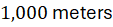 [
 ]), the system initiates reel-in phase: the aircraft's angle of attack is adjusted to minimize aerodynamic lift and drag, and the ground motor consumes a fraction of generated energy to reel the tether back in quickly. The net electrical energy cycle yields high positive power output.
- On-Board Generation (Fly-Gen Mode): Multiple lightweight wind turbine-generator units are mounted directly onto the aircraft's main wing span. As the aircraft flies high-speed crosswind loops, high apparent airflow rotates the on-board rotors, generating electricity in-flight. This electrical energy is transmitted down to the ground station via conductive copper wires integrated directly within the lightweight synthetic mooring tether.
Technical Data Specifications of AWES Parameters
| Airborne Wind Energy Parameter | Engineering Specification Standard |
|---|---|
| Operating Altitude Window |  to  ( 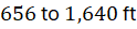 ) above ground |
Aircraft Aerodynamic Lift-to-Drag ( ) |  to  aerodynamic efficiency ratio |
Crosswind Flight Velocity ( ) |  to  ( 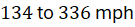 ) |
| Tether Tensile Strength Rating | Ultra-high-molecular-weight polyethylene (UHMWPE / Dyneema) |
| Ground Winch Operating Voltage |  to  DC bus architecture |
| System Capacity Factor | 45% to 60% (higher than fixed wind towers) |
| Reel-Out / Reel-In Cycle Duration | 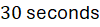 to 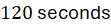 pumping phase |
Tether Materials Science and Aerodynamic Drag Optimization
The structural backbone of any airborne wind energy system is the tether connecting the flying aircraft to the ground station. Tether engineering requires balancing ultra-high tensile strength against aerodynamic drag and mass penalties.
Tethers are fabricated from advanced synthetic fibers such as ultra-high-molecular-weight polyethylene (UHMWPE, marketed as Dyneema) or aramid fibers (Kevlar), exhibiting strength-to-weight ratios fifteen times higher than structural steel. A typical tether maintains a breaking strength exceeding  to
 while maintaining a diameter under
 to
 (
 ).
Minimizing aerodynamic drag along the tether span is critical, as parasitic aerodynamic drag generated by the tether reduces net mechanical power extraction efficiency by 10% to 20%. Engineers apply streamlined aerodynamic fairings or tapered cross-section profiles along the upper tether segments to suppress vortex-induced vibrations (VIV) and transverse drag losses.
Autonomous Flight Control and Grid Integration
Operating tethered aircraft in turbulent high-altitude boundary layers requires highly robust, deterministic autonomous flight control systems (FCS). On-board flight computers integrate high-precision inertial measurement units (IMUs), GNSS positioning, and real-time anemometry sensors to execute closed-loop trajectory tracking algorithms at update frequencies exceeding  .
The flight controller continuously compensates for wind gusts, wind shear gradients, and atmospheric turbulence, ensuring stable crosswind loop execution without human intervention. At the ground station, high-voltage power electronics rectify variable-frequency AC power generated during reel-out cycles into stable DC bus power before inverting it into grid-synchronized AC electricity ( or
 ), enabling seamless integration into utility-scale distribution networks.
The Final Take
Mastering airborne wind energy systems crosswind flight mechanics transforms renewable energy generation by unlocking high-altitude kinetic wind resources inaccessible to conventional tower-mounted turbines. Citing IEA advanced wind technology assessments and academic literature, crosswind looping trajectories amplify apparent wind speeds and power densities by orders of magnitude. By combining ultra-high-molecular-weight polyethylene tethers with automated flight control systems, airborne wind energy establishes an essential technical foundation for next-generation clean power generation.

Comments (0)
Login to leave a comment.
No comments yet. Be the first to share your thoughts!