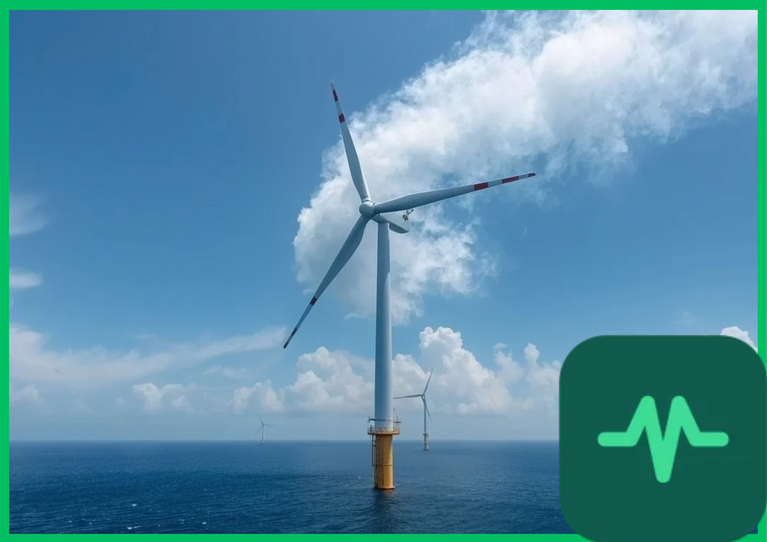
 (
 ) requires precise aerodynamic modeling to maximize power capture coefficients while mitigating extreme structural fatigue loads induced by marine atmospheric boundary layers. Capturing airflow efficiently demands rigorous control over aerodynamic lift coefficients, blade tip speed ratios, wake vortex dynamics, and axial induction factors across changing marine meteorological conditions.
The Betz Limit and Maximum Theoretical Power Conversion Efficiency
The absolute theoretical ceiling for extracting kinetic energy from an open-flow wind stream is defined by Betz's law. Albert Betz established that no wind turbine can convert more than  (approximately
 ) of the kinetic energy passing through the swept rotor area into mechanical shaft power.
The mechanical power ( ) extracted by a wind turbine rotor is expressed mathematically as:
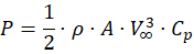
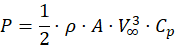
where  represents air density (averaging
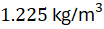 or
 at sea level),
 represents the rotor swept area (
 ),
 denotes the undisturbed free-stream wind velocity, and
 represents the power coefficient. The power coefficient is a function of the axial induction factor (
 ), which quantifies the fractional velocity drop between the free stream and the rotor plane:
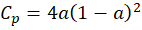
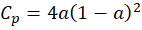
Differentiating this expression with respect to  yields a maximum theoretical power coefficient
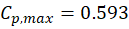 when
 . Modern offshore wind turbines achieve peak operational power coefficients ranging from
 to
 , capturing up to 85% of the theoretical Betz limit under optimal wind velocities.
Aerodynamic Lift Coefficients and Airfoil Cross-Sectional Design
Modern offshore wind turbine blades utilize specialized aerodynamic airfoil cross-sections (such as FFA-W and NACA families) designed to maximize lift-to-drag ratios ( ). Unlike drag-driven devices, modern wind turbines operate on aerodynamic lift principles identical to fixed-wing aircraft.
As airflow passes over the asymmetric airfoil profile, flow velocity accelerates over the curved upper suction surface compared to the lower pressure side, generating a pressure differential that produces aerodynamic lift ( ) perpendicular to the relative wind direction. The lift force is quantified by the lift coefficient (
 ):
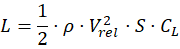
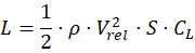
where  is the local relative wind velocity vector and
 is the blade planform area. To maintain high aerodynamic efficiency across the entire blade span—from the root to the
 (
 ) tip—blades incorporate continuous geometric twist and chord taper.
Operating at high Reynolds numbers ( ), offshore blades must prevent boundary layer separation and premature stall. Leading-edge erosion caused by high-velocity droplet impacts in marine environments disrupts laminar flow boundaries, increasing surface drag coefficients and reducing annual energy production (AEP) by 3% to 5%. Advanced composite manufacturing utilizing vacuum-infused glass-fiber and carbon-fiber epoxy matrices preserves exact airfoil tolerances under heavy aerodynamic bending loads.
Blade Tip Speed Ratio ( ) and Rotor Optimization
The tip speed ratio ( ) is a critical dimensionless parameter governing rotor aerodynamic efficiency, defined as the ratio of the tangential speed of the blade tip to the free-stream wind velocity:


where  is the rotor rotational speed in radians per second and
 is the rotor radius. Modern three-bladed offshore wind turbines operate at optimal tip speed ratios between 7 and 9.
Operating at high tip speed ratios maximizes aerodynamic power extraction but introduces severe operational challenges:
- Centrifugal Stress: High rotational speeds generate immense centrifugal forces along the carbon-fiber spar cap structures, requiring robust structural engineering.
- Acoustic Emissions: Blade tip velocities approaching
 to
 (
 to
 ) generate aerodynamic noise via turbulent boundary layer shedding over the trailing edge.
- Cavitation and Erosion: High-speed interaction with rain droplets accelerates leading-edge coating degradation.
Control systems utilize variable-speed generators and collective pitch control actuators to maintain constant optimal tip speed ratios across partial-load wind regimes.
Technical Data Specifications of Offshore Aerodynamic Parameters
| Aerodynamic Parameter | Engineering Specification Range |
|---|---|
| Rotor Diameter |  to  (  to  ) |
| Betz Efficiency Limit | Maximum  ( 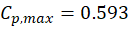 ) |
Operational Power Coefficient ( ) |  to  |
Tip Speed Ratio ( ) | 7 to 9 optimal operating range |
| Blade Tip Velocity |  to  (  to  ) |
Reynolds Number ( ) |  to  along outer span |
Wake Vortex Turbulence and Downwind Farm Interactions
As wind energy is extracted by the rotor blades, a momentum deficit is created downstream, forming a turbulent wake characterized by expanding velocity deficits and spiral tip vortices. In large utility-scale offshore wind farms containing dozens of multi-megawatt turbines, wake interactions significantly impact cumulative energy yields.
Wake decay is governed by ambient atmospheric turbulence intensity and wake expansion coefficients. Within the near-wake region (extending 1 to 2 rotor diameters downstream), blade root and tip vortices dominate flow structures. In the far-wake region (extending beyond 5 rotor diameters), turbulent mixing gradually entrains high-speed kinetic energy from surrounding air masses, restoring wind velocity toward free-stream levels.
When downwind turbines operate inside the wake of upstream machines, they experience reduced wind velocities and severe fatigue-inducing turbulence loads caused by dynamic inflow fluctuations. Academic fluid dynamics research and IEA wind task reports emphasize the deployment of active wake steering strategies—using yaw misalignment to deflect wakes away from downstream rotors—to optimize total farm-level energy capture and reduce structural maintenance expenditures.



Comments (0)
Login to leave a comment.
No comments yet. Be the first to share your thoughts!