 (
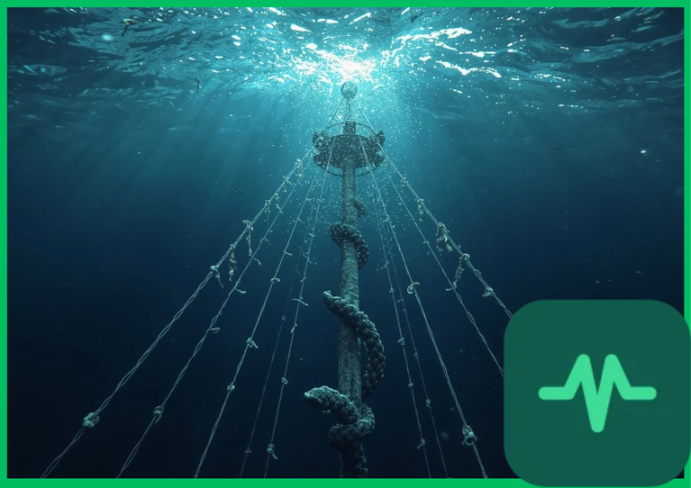
 ). According to International Energy Agency (IEA) marine energy reports, deep-water offshore wind deployment requires robust structural mooring and anchoring architectures capable of withstanding extreme hydrodynamic wave loading, aerodynamic wind thrust vectors, and ocean current shears over 25-year operational lifespans. Maintaining floating substructure stability relies on complex mechanical interactions between floating platforms, catenary mooring lines, tension-leg tendons, and high-capacity seafloor anchors.
Floating Platform Typologies and Substructure Stability Mechanics
Floating offshore wind turbines (FOWTs) operate on structural platforms that achieve hydrostatic stability through ballast distribution and buoyancy forces rather than rigid seabed fixation. Engineering these floating platforms requires categorizing structural architectures into three primary typologies:
- Spar-Buoy Platforms: Utilize deep cylindrical steel hulls ballasted with heavy concrete or mineral aggregates positioned near the bottom of the structure. The center of mass is located significantly below the center of buoyancy, creating a high righting moment that restricts pitch and roll motions. Spar platforms require deep-water anchorages exceeding
 (
 ) and are moored via loose catenary lines.
- Semi-Submersible Platforms: Comprise interconnected large-diameter columns linked by horizontal and diagonal tubular bracing members. Stability is achieved through distributed waterplane area across multiple buoyancy cans rather than a deep draft. Semi-submersibles can operate in intermediate and deep waters (
 to over
 or
 to
 ) and are secured using spread catenary mooring spreads.
- Tension-Leg Platforms (TLPs): Operate on positive buoyancy principles where the upward buoyant force exceeds the total structural and turbine deadweight. High-tension vertical synthetic or steel tendons anchor the platform directly to the seabed, completely suppressing heave, roll, and pitch degrees of freedom while permitting limited surge, sway, and yaw compliance.
Controlling six degrees of freedom—surge, sway, heave, roll, pitch, and yaw—is mandatory to prevent excessive nacelle acceleration and structural fatigue across multi-megawatt turbine blades.
Catenary Mooring Lines Versus Tension-Leg Tendons
The mechanical restoration force holding a floating wind turbine in position is provided by either catenary mooring lines or taut-leg tension tendons, each exhibiting distinct load-displacement dynamics.
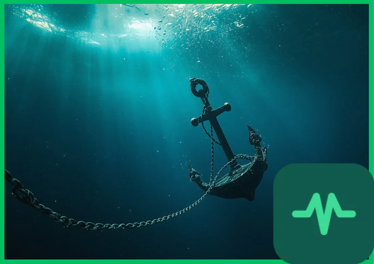
Catenary mooring systems utilize heavy multi-component lines—comprising combinations of stud-link chain, spiral-strand wire rope, and synthetic polyester or nylon segments—laid out radially from the floating platform to seafloor anchors. As environmental loads (wind, waves, and current) push the platform horizontally, the geometric weight of the catenary line lifts off the seabed, providing a progressive restorative restoring force via gravitational sag. Synthetic fiber ropes introduce viscoelastic compliance, damping peak tension loads during severe wave action.
In contrast, tension-leg platforms utilize taut vertical steel pipes or carbon-fiber composite tendons pre-tensioned to a permanent upward buoyancy excess. The axial stiffness of these vertical tendons eliminates heave motion almost entirely. However, rapid wave-frequency wave action induces severe high-frequency cyclic axial stress oscillations, requiring robust fatigue-resistant connector hardware and shock absorbers.
Hydrodynamic Wave Loading and Morison Equation Mechanics
Subsurface structural members experience continuous hydrodynamic wave loading governed by fluid kinematics and potential flow theory. When structural diameters are small relative to incident wave wavelengths (typically  ), hydrodynamic forces are calculated using the Morison equation.
The total hydrodynamic force ( ) per unit length acting on a submerged cylindrical member is the sum of an inertia force component and a drag force component:

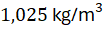
where  represents seawater density (
 or
 ),
 is the outer diameter of the structural member,
 is the fluid particle velocity vector,
 is the fluid particle acceleration vector,
 is the inertia coefficient, and
 is the hydrodynamic drag coefficient.
For large-volume semi-submersible columns where wave diffraction and radiation dominate over viscous drag, potential flow models based on boundary element methods (BEM) compute wave-body interaction transfer functions, predicting wave excitation forces and added mass coefficients across irregular sea states.
Technical Data Specifications of Mooring Systems
| Mooring System Parameter | Engineering Specification Range |
|---|---|
| Operating Water Depth |  to  + (  to  +) |
| Catenary Line Pretension |  to  (  to 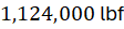 ) |
| TLP Tendon Tension Range |  to  ( 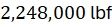 to 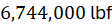 ) |
| Synthetic Rope Elongation | 3% to 10% elastic working stretch |
Maximum Wave Height ( ) | Up to  (  ) extreme storm loading |
| Fatigue Design Life | Minimum 25 years continuous marine exposure |
Dynamic Fatigue and Subsea Anchor Technologies
Seafloor anchor integrity is critical to prevent catastrophic station-keeping failure. Anchor selection is dictated by geotechnical soil properties, shear strength profiles, and ultimate holding capacity requirements:
- Drag-Embedment Anchors (DEAs): Tripping flukes penetrate cohesive clay or sand seabed sediments under horizontal towing loads. DEAs are cost-effective for catenary mooring spreads but exhibit lower uplift resistance.
- Suction Caissons (Suction Piles): Large-diameter open-ended steel cylinders embedded into the seabed via internal pump evacuation. Differential hydrostatic pressure forces the caisson downward. Suction caissons provide massive vertical uplift capacity, making them ideal for taut-leg and semi-submersible mooring spreads.
- Driven Piles: Heavy steel tubular piles driven deep into hard rock or dense sand strata using hydraulic impact hammers, offering extreme load capacity under combined vertical and horizontal stress vectors.
Mooring lines and anchors experience continuous cyclic fatigue damage accumulation driven by millions of wave action cycles. Academic marine engineering research indicates that out-of-plane bending (OPB) at chain-fairlead connections accelerates localized fatigue crack propagation. Implementing active line-tension monitoring sensors, sacrificial zinc or aluminum anode cathodic protection, and specialized swivel connectors mitigates corrosion fatigue, ensuring long-term structural reliability across deep-water wind energy developments.
Comments (0)
Login to leave a comment.
No comments yet. Be the first to share your thoughts!