Hydrodynamic Wave-Structure Interaction and Platform Stability
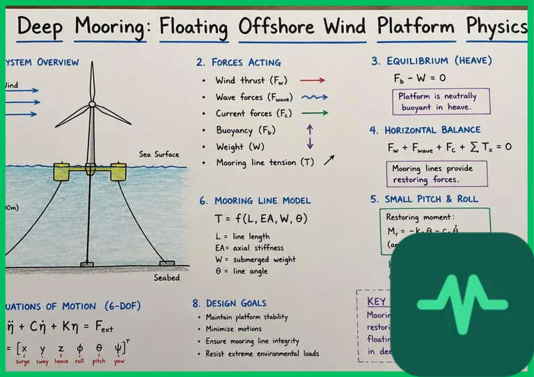
The foundational physical challenge governing floating offshore wind platforms involves managing six degrees of freedom—surge, sway, heave, roll, pitch, and yaw—induced by simultaneous wind aerodynamic thrust loads and ocean wave hydrodynamic forces. As irregular ocean waves propagate past buoyant platform columns, fluid-structure interactions are modeled using potential flow theory and Morison's equation for viscous drag forces on slender cylindrical members.
Semi-submersible platforms rely on large-volume distributed water-plane columns and ballast water management to provide restoring pitching and rolling moments, counteracting aerodynamic overturning moments generated by the 15-megawatt to 20-megawatt turbine rotor positioned 150 meters (492 feet) above the sea surface. Pitch and roll motions must be constrained within tight operational boundaries (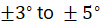 ) to prevent excessive gyroscopic fatigue loads on the drivetrain, main shaft bearings, and planetary gearbox components.
Wave diffraction and radiation forces excite platform oscillation frequencies, requiring tuned mass dampers (TMDs) or active ballast control systems to suppress resonant wave amplification and damp structural motion.
Catenary Line Physics and Mooring Tension Dynamics
Restraining massive floating platforms against severe storm surges, extreme wave heights (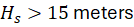 [49.2 feet]), and hurricane-force wind loads requires engineered mooring spreads governed by catenary line physics. A standard catenary mooring line consists of heavy steel chain, wire rope, or synthetic fiber segments whose weight rests partially on the seabed, forming a smooth mathematical catenary curve.
As wind and wave thrust pushes the floating platform horizontally, the platform undergoes surge and sway displacement, lifting a portion of the heavy mooring chain off the seabed. The gravitational weight of the suspended chain segment provides a restoring horizontal restoring force that pulls the platform back to its equilibrium position. The horizontal tension component ( ) and spatial line configuration are formulated mathematically by balancing distributed line weight (
 ) and geometric span:
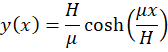
As dynamic wave action excites the platform, instantaneous mooring line tension fluctuates violently between slack states and extreme peak tensile loads. Synthetic fiber ropes—such as polyester or aramid—introduce high elasticity, stretching up to 10% under peak loads to absorb kinetic shock energy and reduce maximum anchor uplift loads.
Technical Data Specifications of Floating Offshore Wind Mooring Systems
| Floating Wind Mooring Parameter | Engineering & Marine Specification Standard |
|---|---|
| Minimum Water Depth Operational Threshold | 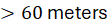 (  ) deep-water deployment |
| Platform Degrees of Freedom Controlled | 6 DOF (Surge, Sway, Heave, Roll, Pitch, Yaw) |
| Operational Pitch and Roll Motion Limit | 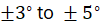 maximum inclination threshold |
| Mooring Line Spread Configuration | 3- to 4-point catenary or taut-leg anchoring system |
| Synthetic Rope Elasticity Stretch Limit | Up to 10% elongation under extreme peak tension |
| Dynamic Subsea Cable Voltage Rating |  to  alternating current (AC) |
| Anchor Holding Capacity Standard | Drag-embedment or suction caissons ( load) |
Dynamic Cable Fatigue and Subsea Umbilical Mechanics
Beyond structural mooring lines, floating offshore wind platforms must transmit high-voltage electrical power to the seabed via dynamic subsea power cables (inter-array and export umbilicals). These dynamic cables experience continuous cyclic bending and twisting stresses as the floating platform responds to wave-induced motions.
Dynamic cable fatigue is driven by multi-axis bending fatigue, vortex-induced vibrations (VIV), and snap-load phenomena occurring when slack mooring or umbilical segments snap taut under rapid wave troughs. Engineers utilize rainflow counting algorithms and Palmgren-Miner linear damage hypotheses to calculate cumulative fatigue damage coefficients over 25-year operational lifespans.
Subsea umbilicals incorporate specialized polyurethane outer jackets, lead moisture barriers, fiber optic temperature-sensing channels, and copper conductor helical winding geometries to withstand continuous mechanical flexing without dielectric insulation breakdown.
Anchor Systems and Seabed Interaction Mechanics
Anchoring deep-water floating wind platforms requires matching anchor holding capacity to site-specific seabed geotechnical conditions. Common anchor designs include drag-embedment anchors, high-capacity suction caissons, and driven piles.
In soft clay seabeds, suction caissons—large steel cylinders penetrating 15 to 30 meters (49.2 to 98.4 feet) into the sediment—evacuate internal water to create negative pressure differentials, achieving massive holding capacities against vertical pull-out forces. In sandy or rocky seabeds, dynamically embedded plate anchors or driven piles provide the necessary structural resistance against cyclic uplift forces transmitted through taut synthetic or chain mooring lines, ensuring absolute positional stability across diverse marine environments.
Comments (0)
Login to leave a comment.
No comments yet. Be the first to share your thoughts!