 ) and oxygen (
 ). According to International Energy Agency (IEA) hydrogen technology roadmaps and global renewable deployment trackers, scaling up green hydrogen generation is an absolute engineering prerequisite for decarbonizing heavy industrial sectors such as steel manufacturing, ammonia synthesis, and long-haul maritime shipping. Achieving commercial parity with fossil-derived gray hydrogen requires rigorous optimization of thermodynamic voltage thresholds, catalyst kinetics, faradaic efficiencies, and multi-megawatt electrolyzer stack topologies.
Thermodynamic Potentials and Reversible Cell Voltages
The fundamental thermodynamics governing water splitting are derived from the Gibbs free energy change ( ) of the overall chemical reaction:
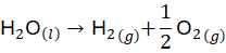
The standard Gibbs free energy change for liquid water splitting at  (
 ) and
 pressure is
 . The minimum theoretical electrical potential difference required to drive this reaction—known as the reversible cell voltage (
 )—is calculated via the Nernst equation:
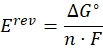
where  represents the number of electrons transferred per mole of water split (
 ), and
 denotes the Faraday constant (
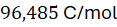 ). Under standard conditions, the reversible cell voltage evaluates to
 .
However, practical operation requires accounting for the total enthalpy change ( ), which includes the thermal energy demand (
 ) of the reaction. This yields the thermoneutral cell voltage (
 ) at standard temperature:
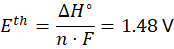
Operating an electrolyzer below  requires external thermal energy input to sustain the endothermic water-splitting process, whereas operating above
 generates excess internal heat through overpotentials and ohmic resistance.
Electrolyzer Typologies: PEM, Alkaline, and Solid Oxide Systems
Commercial green hydrogen production utilizes three primary electrolyzer technologies, each characterized by distinct electrolyte compositions, operating temperatures, and dynamic load response capabilities:
- Proton Exchange Membrane (PEM) Electrolyzers: Utilize a solid polymer electrolyte membrane (typically sulfonated tetrafluoroethylene-based fluoropolymer, such as Nafion) that conducts protons (
 ) from the anode to the cathode. Operates at current densities between
 and
 , temperatures of
 to
 (
 to
 ), and pressures up to
 (
 ). PEM systems offer rapid cold-start capabilities and dynamic load-following performance ideal for coupling with intermittent wind and solar power generation.
- Alkaline Water Electrolyzers (AWE): Utilize a liquid potassium hydroxide (
 ) aqueous solution (typically 20% to 30% concentration) as the ionic conductor, separated by a porous ceramic diaphragm. Operates at lower current densities (
 to
 ) and temperatures of
 to
 (
 to
 ). AWE systems avoid expensive noble-metal catalysts, utilizing nickel-based mesh electrodes, but exhibit slower dynamic response times.
- Solid Oxide Electrolyzer Cells (SOEC): Utilize a ceramic solid oxide membrane (such as yttria-stabilized zirconia, YSZ) operating at high temperatures between
 and
 (
 to
 ). High-temperature operation reduces electrical energy demand by substituting thermal energy input, achieving electrical efficiencies exceeding 85% higher heating value (HHV).
Overpotentials and Kinetic Polarization Losses
Real-world electrolyzer stacks fail to operate at the thermodynamic thermoneutral voltage ( ) due to polarization losses. Total cell operating voltage (
 ) is the sum of the thermodynamic open-circuit voltage and three primary overpotential components:
- Activation Overpotential (
 ): Energy barrier required to initiate electron transfer and drive electrochemical reaction kinetics at the anode and cathode interfaces. Sluggish oxygen evolution reaction (OER) kinetics at the anode dominate activation losses, requiring precious metal catalysts such as iridium oxide (
 ) or ruthenium oxide (
 ). Cathode hydrogen evolution reaction (HER) kinetics are significantly faster, utilizing platinum nanoparticles supported on carbon.
- Ohmic Overpotential (
 ): Resistance to ionic transport through the electrolyte membrane or liquid solution, combined with electronic resistance across bipolar plates, current collectors, and terminal busbars. Minimized by reducing membrane thickness down to
 to
 and optimizing titanium bipolar plate coatings.
- Mass Transport Overpotential (
 ): Voltage penalty incurred when gas bubble generation (
 and
 ) obstructs active electrode surface areas, inhibiting fresh reactant water diffusion to catalytic sites at high current densities.
Faraday Efficiency and Specific Energy Consumption Metrics
The overall conversion efficiency of green hydrogen production electrolysis is evaluated using Faradaic efficiency ( ) and specific energy consumption (
 ). Faradaic efficiency measures the ratio of actual hydrogen gas mass produced to the theoretical maximum yield predicted by Faraday's law of electrolysis based on total integrated electrical current:
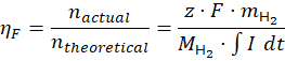
Modern industrial PEM and alkaline electrolyzers achieve high Faradaic efficiencies between 95% and 99% under optimal operating conditions. Gas crossover—where minor quantities of hydrogen diffuse through the membrane into the oxygen stream (or vice versa)—represents the primary source of Faradaic loss, requiring continuous monitoring via inline gas chromatographs to maintain safety limits below the 4% lower flammability limit (LFL).
Specific energy consumption quantifies the electrical energy required to produce one kilogram of hydrogen gas, expressed in kilowatt-hours per kilogram ( ). Operating at a cell voltage of
 yields a specific energy consumption of approximately
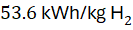 , compared to the theoretical lower heating value (LHV) energy threshold of
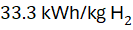 (
 ).
Balance of Plant (BoP) Integration and Renewable Coupling
An industrial green hydrogen production facility consists of the electrolyzer stack integrated with a complex Balance of Plant (BoP) infrastructure. The BoP subsystem comprises deionized water purification units (maintaining feed water conductivity below  to prevent catalyst poisoning), liquid-gas separation skids, catalytic de-oxo purifiers, multi-stage compressor units, and thermal management heat exchangers.
Coupling electrolyzers directly to variable renewable energy sources—such as photovoltaic solar arrays and wind farms—introduces operational challenges. Intermittent power fluctuations cause transient thermal stress, mechanical pressure differentials across the membrane, and accelerated catalyst degradation. Advanced power electronics, including insulated gate bipolar transistor (IGBT) rectifiers and modular DC-DC buck converters, smooth power supply fluctuations and maintain precise current regulation across variable generation profiles.
Empirical Research and Environmental Assessments
Quantitative environmental assessments published by the IEA and United Nations Environment Programme (UNEP) confirm that scaling up green hydrogen production powered by zero-carbon electricity slashes lifecycle greenhouse gas emissions to less than  per kilogram of hydrogen produced, compared to
 for steam methane reforming (SMR) without carbon capture. Academic research materials science consortia focus on earth-abundant catalyst development—replacing scarce iridium and platinum with nickel-iron-molybdenum alloys—to reduce capital expenditures and accelerate global green hydrogen infrastructure deployment.

Comments (0)
Login to leave a comment.
No comments yet. Be the first to share your thoughts!