 (
 ) or across subsea marine channels. Alternating current lines suffer from continuous reactive power charging currents, dielectric hysteresis losses in cable insulation, and skin effect resistance heating that dissipates substantial energy. In contrast, high-voltage direct current (HVDC) transmission eliminates reactive power losses and skin effect resistance, achieving total line energy losses as low as 3% per
 (
 ), establishing an indispensable technical baseline for long-distance power transfer.
Alternating Current Limitations and Skin Effect Physics
The foundational physical limitation driving the adoption of HVDC transmission is the inherent electrical impedance behavior of alternating current (AC) lines operating at fixed frequencies ( or
 ). In an HVAC overhead line or subterranean cable, the alternating electric and magnetic fields induce reactive capacitive charging currents (
 ) between the conductor and the earth or surrounding shield. These charging currents consume a significant fraction of the conductor's ampacity limit, reducing active power transfer capacity over extended distances.
Furthermore, alternating current induces electromagnetic phenomena known as the skin effect and proximity effect. Because alternating magnetic fields generate eddy currents within the interior of solid conductors, current density concentrates heavily at the outer periphery (skin) of the metal strand. The effective AC resistance ( ) of a copper or aluminum conductor increases significantly compared to its direct current resistance (
 ):
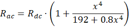
where  is a skin effect parameter scaled to conductor radius, frequency, and material resistivity. In direct current transmission systems, electrons flow uniformly across the entire cross-sectional area of the conductor, eliminating skin effect resistance inflation and minimizing ohmic joule heating (
 ) over multi-hundred-kilometer routes.
Converter Station Efficiency and LCC Versus VSC Topologies
While HVDC transmission lines exhibit drastically lower line losses than HVAC alternatives, power conversion infrastructure introduces fixed conversion losses at both the sending (rectifier) and receiving (inverter) substations. Modern HVDC systems utilize two primary power electronics converter topologies:
- Line-Commutated Converters (LCC): Utilize high-power thyristor semiconductor switches operated via grid-supplied commutation voltages. LCC systems achieve high power ratings (exceeding
 to
 ) and low converter station losses (
 per station), but require strong receiving AC grids and are susceptible to catastrophic commutation failure during AC voltage drops.
- Voltage-Source Converters (VSC): Utilize insulated-gate bipolar transistors (IGBTs) or silicon carbide (SiC) semiconductor switches combined with pulse-width modulation (PWM) control. VSC systems operate independently of weak AC networks, provide black-start capability, and regulate active and reactive power instantaneously. Although VSC stations incur slightly higher conversion losses (
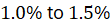 per station) due to high-frequency switching, multi-level modular converter (MMC) topologies reduce harmonic distortion and filter requirements significantly.
Technical Data Specifications of HVDC Transmission Parameters
| HVDC Transmission Parameter | Engineering Specification Standard |
|---|---|
| Typical Operating Voltage Range |  to  DC bipolar lines |
| Line Transmission Energy Losses |  (  ) distance |
| Converter Station Power Losses | 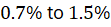 conversion loss per terminal |
| Maximum Subsea Cable Depth Limit | Up to 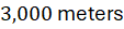 (  ) underwater |
| Conductor Material Composition | High-purity annealed copper or aluminum alloy reinforced with steel |
| Semiconductor Switching Technology | Thyristor (LCC) / IGBT Modular Multilevel Converters (VSC) |
| Distance Break-Even Threshold |  (  ) overground /  (  ) subsea |
Corona Discharge Suppression and Conductor Physics
Operating overhead direct current transmission lines at extreme voltage potentials ( to
 DC) generates intense surface electric field gradients that can exceed the dielectric breakdown strength of ambient air, triggering corona discharge phenomena. Corona discharge ionizes air molecules surrounding the conductor surface, resulting in audible noise, radio frequency interference (RFI), ozone generation, and continuous active power energy losses.
Electrical engineers suppress corona discharge by managing conductor surface electric field gradients below the critical ionization threshold ( at standard atmospheric pressure). Mitigation strategies include utilizing bundled conductor configurations (placing two, four, or six sub-conductors spaced apart within a single phase via metallic spacers) to increase the effective electrical radius of the conductor bundle. Furthermore, smooth, polished conductor surface finishes and specialized grading rings eliminate sharp microscopic surface asperities that concentrate electrostatic stress fields.
Submarine and Underground Cable Insulation Mechanics
For long-distance bulk power transfers traversing marine straits or densely populated urban corridors, overhead transmission lines are replaced by high-voltage direct current submarine and underground cables. Insulation mechanics differ fundamentally between AC and DC cables. In an AC cable, insulation is subjected to alternating capacitive stress and continuous dielectric heating. In contrast, a DC cable insulation matrix experiences static electric field stress governed by material electrical resistivity ( ), which varies inversely with temperature.
Modern HVDC cables utilize extruded cross-linked polyethylene (XLPE) or mass-impregnated paper insulation. Extruded XLPE insulation offers high thermal stability, withstanding conductor operating temperatures up to  (
 ) without mechanical degradation. However, direct current electrical stress causes space charge accumulation—the trapping of free electrical charges within the polyethylene crystal lattice—which creates internal local electric field distortions. Engineers incorporate specialized nanoparticle additives and voltage-stabilizing chemical scavengers into the XLPE polymer matrix to suppress space charge formation, ensuring multi-decade dielectric reliability under harsh subsea operational pressures.
Long-Distance Power Transfer Economics and Break-Even Analysis
Evaluating the deployment of HVDC transmission requires balancing high initial capital expenditures ( ) against long-term operational expenditure (
 ) savings over extended operational lifespans. Constructing HVDC converter stations incurs substantial capital outlays. Consequently, short-distance transmission lines favor conventional HVAC systems due to lower terminal equipment costs.
However, as transmission distance increases past the break-even threshold—approximately  (
 ) for overhead land lines and
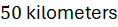 (
 ) for subsea marine cables—the cumulative cost of line energy losses and reactive power compensation in HVAC systems surpasses the fixed capital cost of HVDC converter stations. Citing IEA grid infrastructure roadmaps, deploying ultra-high-voltage direct current (
 ) lines operating at
 to
 DC enables bulk power transfers exceeding
 over multi-thousand-kilometer corridors with minimal transmission attenuation, connecting remote renewable energy generation hubs directly to urban load centers.
The Final Take
Mastering high voltage direct current transmission line losses advances bulk electrical grid infrastructure by enabling low-loss, intercontinental power transfer across thousands of kilometers. Citing IEA grid integration assessments and electrical power literature, eliminating skin effect resistance, optimizing VSC converter station efficiency, and deploying advanced XLPE submarine cable insulation minimizes energy dissipation. By suppressing corona discharge and balancing capital economics, HVDC transmission establishes an indispensable foundation for global clean energy grid interconnections.

Comments (0)
Login to leave a comment.
No comments yet. Be the first to share your thoughts!