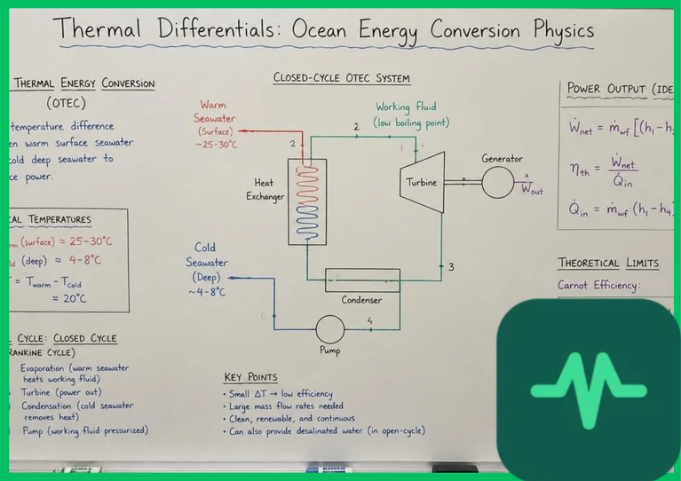
Thermodynamic Foundations and the Carnot Cycle Limit
The theoretical efficiency of any heat engine operating between two thermal reservoirs is governed by the Carnot efficiency limit (ηCarnot\eta_{Carnot}ηCarnot), expressed as:
ηCarnot=1−TcoldThot\eta_{Carnot} = 1 - \frac{T_{cold}}{T_{hot}}ηCarnot=1−ThotTcold
where ThotT_{hot}Thot represents the absolute temperature of warm surface seawater in Kelvin (K\text{K}K) and TcoldT_{cold}Tcold represents the absolute temperature of deep ocean water. Tropical ocean environments typically feature surface water temperatures between 25∘C25^\circ\text{C}25∘C and 28∘C28^\circ\text{C}28∘C (77∘F77^\circ\text{F}77∘F to 82.4∘F82.4^\circ\text{F}82.4∘F, or approximately 298 K298\text{ K}298 K to 301 K301\text{ K}301 K), while deep ocean water drawn from depths of 1,000 m1,000\text{ m}1,000 m (3,280 ft3,280\text{ ft}3,280 ft) maintains consistent cold temperatures between 4∘C4^\circ\text{C}4∘C and 7∘C7^\circ\text{C}7∘C (39.2∘F39.2^\circ\text{F}39.2∘F to 44.6∘F44.6^\circ\text{F}44.6∘F, or approximately 277 K277\text{ K}277 K to 280 K280\text{ K}280 K).
Substituting these values into the Carnot equation yields an ideal theoretical efficiency ceiling between 6% and 8%:
ηCarnot=1−278 K298 K=0.067 (or 6.7%)\eta_{Carnot} = 1 - \frac{278\text{ K}}{298\text{ K}} = 0.067 \text{ (or 6.7\%)}ηCarnot=1−298 K278 K=0.067 (or 6.7%)
Because actual OTEC power cycles operate with real-world thermal losses across heat exchangers, turbine inefficiencies, and parasitic pumping power loads required to lift deep water, net thermal conversion efficiencies typically range between 2.5% and 3.5%. Despite low thermal conversion coefficients, OTEC plants compensate for modest per-unit efficiency by exploiting an inexhaustible, continuous thermal reservoir.
OTEC System Configurations: Closed, Open, and Hybrid Cycles
Engineering ocean thermal energy conversion systems involves three primary thermodynamic configurations, each tailored to specific fluid handling and power generation requirements:
- Closed-Cycle (Anderson Cycle): Utilizes a working fluid with a low boiling point—such as anhydrous ammonia (NH3\text{NH}_3NH3), propane (C3H8\text{C}_3\text{H}_8C3H8), or hydrofluorocarbons—circulating in a sealed thermodynamic loop. Warm surface seawater flows through an evaporator, transferring thermal energy to vaporize the working fluid. The expanding vapor drives a high-efficiency radial-inflow turbine connected to an electrical generator. The vapor then passes through a condenser cooled by deep-ocean water, returning to liquid phase before being pumped back to the evaporator.
- Open-Cycle (Claude Cycle): Bypasses intermediate working fluids entirely by utilizing warm surface seawater as the working fluid itself. Seawater enters a flash evaporator operating under partial vacuum pressure, where a fraction of the water vaporizes into steam. This low-pressure steam expands through a massive turbine. The steam is subsequently condensed either by direct contact with cold deep-ocean water in a direct-contact condenser or via surface condensers, simultaneously producing high-purity desalinated freshwater as a valuable co-product.
- Hybrid-Cycle: Combines closed-cycle power generation with open-cycle flash desalination. Warm seawater passes through a flash evaporator to produce desalinated steam before entering a closed-cycle ammonia evaporator stage, optimizing both electricity output and potable water production.
Technical Performance Metrics of OTEC System Architectures
| System Parameter | Closed-Cycle (Anderson Cycle) | Open-Cycle (Claude Cycle) | Hybrid-Cycle Configuration |
|---|---|---|---|
| Working Fluid | Anhydrous ammonia or fluorocarbons | Direct seawater vapor (steam) | Ammonia working fluid + seawater flash steam |
| Evaporator Design | Shell-and-tube or plate heat exchangers | Flash evaporation vacuum chambers | Multi-stage flash chamber plus shell-and-tube |
| Turbine Scale | Compact, high-pressure turbine runners | Massive volumetric flow, low-pressure turbines | Combined dual-turbine or integrated power stage |
| Co-Products | Electricity generation only | Electricity plus desalinated freshwater | Optimized electricity and high-purity water yield |
| Parasitic Load | 25% to 35% for seawater pumps | 30% to 40% for vacuum and water pumps | 30% to 42% total auxiliary pumping load |
Deep Ocean Pipeline Mechanics and Seawater Hydraulics
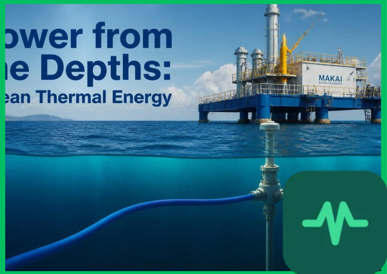
A critical structural engineering component of any OTEC installation is the cold water pipe (CWP). Transporting cold water from depths of 800 m800\text{ m}800 m to 1,000 m1,000\text{ m}1,000 m (2,625 ft2,625\text{ ft}2,625 ft to 3,280 ft3,280\text{ ft}3,280 ft) requires large-diameter conduits ranging from 2 m2\text{ m}2 m to 6 m6\text{ m}6 m (6.5 ft6.5\text{ ft}6.5 ft to 19.7 ft19.7\text{ ft}19.7 ft) across vertical spans exceeding one kilometer.
Material selection for the CWP must withstand severe hydrostatic pressure gradients, ocean current shear stresses, and biofouling. Engineers utilize high-density polyethylene (HDPE), fiber-reinforced polymer (FRP) composites, and concrete-coated steel structures. Fluid friction losses inside the pipe are modeled using the Darcy-Weisbach equation. Minimizing head loss requires smooth inner pipe surfaces and optimized cross-sectional diameters to prevent excessive parasitic pumping power consumption, which can consume 30% to 40% of gross turbine generation.
Heat Exchanger Optimization and Biofouling Mitigation
Because the temperature differential is small, heat exchangers represent the largest capital expenditure (CapEx) item in an OTEC facility. High heat transfer coefficients are mandatory to maximize thermal energy recovery across narrow temperature gradients. Titanium alloy plates or specialized stainless steel plate-fin heat exchangers are deployed to prevent saltwater corrosion and galvanic degradation.
Marine biofouling poses an operational threat to heat exchanger efficiency. Microscopic marine organisms, algae, and bacteria adhere to heat transfer surfaces, increasing thermal contact resistance and reducing overall heat transfer coefficients (UUU-values). Facilities implement continuous or intermittent mechanical cleaning systems—such as circulating sponge balls through tube bundles—alongside environmentally safe chlorination or ultrasonic anti-fouling systems to maintain peak thermal performance.
Environmental Assessments and UNEP Governance Guidelines
Quantitative environmental evaluations published by the United Nations Environment Programme (UNEP) and academic marine research consortia indicate that OTEC operations generate minimal net greenhouse gas emissions while exhibiting unique local ecological interactions. Pumping large volumes of deep ocean water introduces cold, nutrient-rich water into surface layers. When managed correctly, this artificial upwelling supports aquaculture and marine biomass cultivation. However, unmitigated discharge can alter localized surface water temperatures and pH balances. Environmental monitoring frameworks mandate deep-water injection return protocols—discharging mixed effluent at intermediate depths (100 m100\text{ m}100 m to 200 m200\text{ m}200 m or 328 ft328\text{ ft}328 ft to 656 ft656\text{ ft}656 ft) where thermal and density characteristics match the surrounding water column, preserving upper pelagic ecosystem stability.

Comments (0)
Login to leave a comment.
No comments yet. Be the first to share your thoughts!