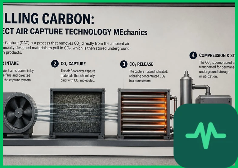
Direct air capture technology mechanics extract carbon dioxide ($\text{CO}_2$) directly from ambient air, where its current concentration exceeds 420 parts per million ($\text{ppm}$), representing a dilute gas mixture compared to industrial point sources like flue gas streams ($10\%$ to $15\%$ $\text{CO}_2$). According to International Energy Agency (IEA) carbon management reports and United Nations Environment Programme (UNEP) environmental assessments, gigaton-scale atmospheric $\text{CO}_2$ removal is an essential complement to industrial emission reductions to mitigate irreversible climate tipping points. Engineering these capture systems requires overcoming severe thermodynamic constraints, managing high specific energy consumption rates, and optimizing chemical contactor surface areas, mass transfer coefficients, and thermal regeneration loops.
Thermodynamic Minimum Work and Dilute Separation Realities
The primary engineering challenge of direct air capture stems from entropy of mixing. Separating a trace gas from a dilute ambient mixture requires a fundamental thermodynamic energy penalty governed by the ideal gas law and Gibbs free energy of mixing ($\Delta G_{mix}$).
The theoretical minimum separation work ($W_{min}$) required to extract one mole of $\text{CO}_2$ from ambient air at a mole fraction ($y_{\text{CO}_2} \approx 0.00042$) at standard temperature ($298.15\text{ K}$ or $25^\circ\text{C}$ [$77^\circ\text{F}$]) is calculated via:
$$W_{min} = -R \cdot T \cdot \ln\left(\frac{1}{y_{\text{CO}_2}}\right)$$
where $R$ represents the universal gas constant ($8.314\text{ J/(mol}\cdot\text{K)}$) and $T$ denotes absolute temperature. This minimum thermodynamic work evaluates to approximately $19.4\text{ kJ/mol}$, or roughly $440\text{ kJ}$ per kilogram ($400\text{ BTU/lb}$) of pure $\text{CO}_2$ captured.
In contrast, extracting $\text{CO}_2$ from concentrated point-source flue gas requires significantly lower theoretical minimum work due to higher partial pressure gradients. Real-world direct air capture systems operate with thermodynamic efficiencies between 10% and 20%, resulting in actual specific energy requirements ranging from $1.5\text{ GJ}$ to $10\text{ GJ}$ of thermal and electrical energy per metric ton of $\text{CO}_2$ captured ($1.3\text{ million}$ to $9.5\text{ million BTU}$ per short ton). Bridging this thermodynamic gap demands advanced contactor design and efficient regeneration chemistry.
Liquid Solvent Systems: Contactor Towers and Calcination Loops
Liquid-based direct air capture systems utilize aqueous alkaline solutions, predominantly potassium hydroxide ($\text{KOH}$) or sodium hydroxide ($\text{NaOH}$), contacting ambient air inside large industrial contractor towers packed with structured plastic media to maximize gas-liquid interfacial area.
Atmospheric air is blown through the contactor using large multi-megawatt axial fans, where $\text{CO}_2$ reacts chemically with the liquid solvent to form soluble carbonates:
$$\text{CO}_2\text{ (g)} + 2\text{KOH}\text{ (aq)} \rightarrow \text{K}_2\text{CO}_3\text{ (aq)} + \text{H}_2\text{O}\text{ (l)}$$
Because direct air capture requires regenerating the alkaline solvent continuously, liquid systems incorporate a complex, high-temperature calcination loop:
Causticization Stage: The potassium carbonate solution is mixed with calcium hydroxide ($\text{Ca(OH)}_2$), precipitating solid calcium carbonate ($\text{CaCO}_3$) and regenerating potassium hydroxide for return to the air contactor.
Calcinator Kiln: Solid calcium carbonate is transferred into a natural-gas-fired or electrically heated calcination kiln operating at extreme temperatures between $850^\circ\text{C}$ and $900^\circ\text{C}$ ($1,562^\circ\text{F}$ to $1,652^\circ\text{F}$).
Thermal Decomposition: High-temperature thermal energy decomposes calcium carbonate into pure gaseous $\text{CO}_2$ and calcium oxide ($\text{CaO}$), which is subsequently slaked with water to regenerate $\text{Ca(OH)}_2$.
While liquid solvent systems benefit from high chemical reaction rates and robust contactor stability, the high-temperature calcination step imposes a massive thermal energy penalty, requiring dedicated low-carbon heat sources or oxy-fuel combustion loops.
Solid Sorbent Systems: Vacuum-Temperature Swing Adsorption (VTSA)
To circumvent the intensive high-temperature calcination requirements of liquid systems, solid sorbent direct air capture architectures utilize porous solid substrates chemically functionalized with amine groups (primary, secondary, or tertiary amines) or metal-organic frameworks (MOFs). These solid sorbents exhibit high internal surface areas exceeding $2,000\text{ m}^2/\text{g}$ ($9,760\text{ ft}^2/\text{oz}$).
Solid sorbent contactors operate via cyclic Vacuum-Temperature Swing Adsorption (VTSA) protocols:
Adsorption Phase: Ambient air passes through modular sorbent blocks at ambient temperatures. $\text{CO}_2$ molecules bind reversibly to amine active sites via weak chemisorption bonds.
Evacuation Phase: The modular contactor chamber is sealed and evacuated using industrial vacuum pumps to lower total pressure and desorb loosely bound gas.
Thermal Desorption: Low-grade waste heat or electrical resistance heating raises sorbent temperatures to between $80^\circ\text{C}$ and $120^\circ\text{C}$ ($176^\circ\text{F}$ to $248^\circ\text{F}$). This moderate thermal input breaks the amine-$\text{CO}_2$ bonds, releasing a concentrated stream of pure $\text{CO}_2$ gas.
Solid sorbent systems operate at significantly lower regeneration temperatures than liquid systems, allowing integration with industrial waste heat streams or surplus renewable electricity. However, solid sorbents face mechanical attrition, binder degradation, and oxidative aging over thousands of adsorption-desorption cycles.
Technical Performance Metrics of Direct Air Capture Architectures
Performance Parameter | Liquid Solvent Systems (KOH/CaCO3) | Solid Sorbent Systems (Amine/MOF) |
|---|---|---|
Operating Temperature | Ambient absorption; $900^\circ\text{C}$ ($1,652^\circ\text{F}$) calciner | Ambient adsorption; $80^\circ\text{C}$ to $120^\circ\text{C}$ desorption |
Thermal Energy Input | $4.0\text{ GJ}$ to $10.0\text{ GJ per metric ton CO}_2$ | $1.5\text{ GJ}$ to $3.5\text{ GJ per metric ton CO}_2$ |
Electrical Energy Input | $250\text{ kWh}$ to $400\text{ kWh per metric ton CO}_2$ | $300\text{ kWh}$ to $600\text{ kWh per metric ton CO}_2$ |
Sorbent / Solvent Lifespan | Multi-year liquid makeup; high chemical stability | 1 to 5 years before structural attrition and replacement |
Water Consumption | High evaporative water loss ($1\text{ to }5\text{ tons H}_2\text{O}$ per ton $\text{CO}_2$) | Low-to-moderate water usage; closed-loop moisture recovery |
Compression, Pipeline Transport, and Geological Mineralization
Regardless of whether $\text{CO}_2$ is captured via liquid solvent loops or solid sorbent VTSA modules, the recovered gas must undergo multi-stage compression to achieve supercritical fluid states for pipeline transport and permanent geological sequestration.
The supercritical phase transition occurs at $31.1^\circ\text{C}$ ($88.0^\circ\text{F}$) and $7.39\text{ MPa}$ ($1,073\text{ psi}$). Multi-stage centrifugal compressors elevate captured gas pressures to $15\text{ MPa}$ to $25\text{ MPa}$ ($2,175\text{ psi}$ to $3,625\text{ psi}$). At these elevated pressures, supercritical $\text{CO}_2$ exhibits high density and low viscosity, optimizing pipeline hydrodynamic flow efficiency over long distances.
For permanent disposal, supercritical $\text{CO}_2$ is injected into deep saline sedimentary formations located $1,000\text{ m}$ to $3,000\text{ m}$ ($3,280\text{ ft}$ to $9,840\text{ ft}$) beneath impermeable caprock strata. Alternatively, in basalt formations, injected $\text{CO}_2$ dissolves into water and reacts with calcium, magnesium, and iron silicates, inducing permanent in-situ mineralization into solid carbonate rock matrices within two years.
Parasitic Energy Penalties and Global Scaling Roadmaps
Quantitative lifecycle assessments published by the IEA and academic research consortia indicate that direct air capture installations require substantial parasitic energy inputs. If DAC facilities draw electricity and heat from fossil-fueled grids, net carbon removal efficiency drops precipitously. Consequently, commercial DAC plants must couple directly with dedicated zero-carbon energy sources, such as geothermal power plants, concentrated solar thermal arrays, or nuclear reactors.
Scaling direct air capture from current pilot facilities capturing thousands of tons annually to gigaton-scale deployment requires addressing major capital expenditure (CapEx) hurdles, supply chain constraints for specialized catalysts, and large land-use footprints. Academic material science research continues to develop advanced metal-organic frameworks and electro-swing adsorption cells, driving down regeneration energy requirements and capital costs to secure a permanent role for direct air capture within global net-zero emissions frameworks.
Comments (0)
Login to leave a comment.
No comments yet. Be the first to share your thoughts!