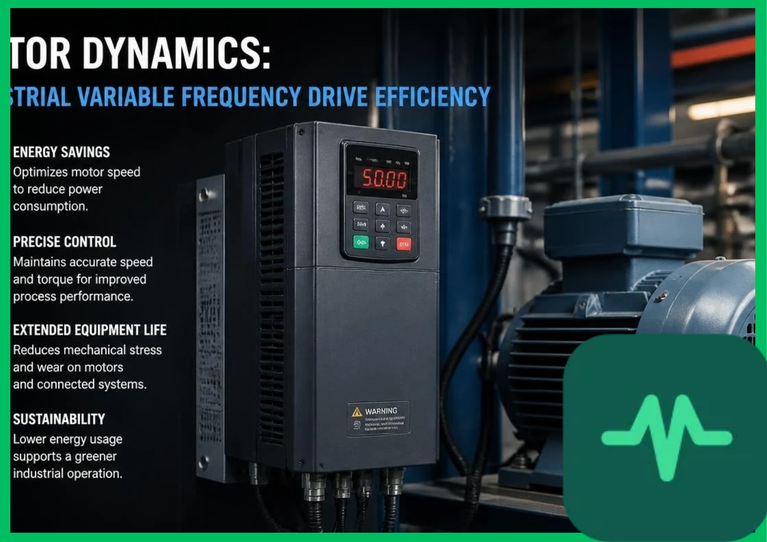
Centrifugal Pump Affinity Laws and Hydraulic Power Mechanics
The foundational engineering rationale driving variable frequency drive efficiency is the set of fluid-dynamic affinity laws governing centrifugal pumps, blowers, and fans. The hydraulic power ( ) required to drive a centrifugal load scales non-linearly with rotational speed (
 ). The affinity equations express these relationships explicitly:
- Flow Rate (
 ): Proportional directly to rotational speed:
- Head Pressure (
 ): Proportional to the square of rotational speed:
- Power Consumption (
 ): Proportional to the cube of rotational speed:


Under a fixed-speed configuration, a motor runs constantly at 100% speed while mechanical throttle valves restrict flow, maintaining high power draw regardless of actual demand. When a VFD reduces motor speed by 20% (operating at 80% speed or  ), the power consumption drops cubically to
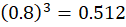 , or 51.2% of full load power. This cubic power reduction eliminates throttling waste, delivering substantial electrical energy savings across industrial fluid transport systems.
Pulse-Width Modulation and Inverter Conversion Architecture
A variable frequency drive operates by converting fixed-frequency alternating current (AC) line power into direct current (DC) via an active rectifier bridge, smoothing the DC bus voltage with electrolytic capacitors, and subsequently synthesizing a variable-frequency, variable-voltage AC output using high-frequency pulse-width modulation (PWM).
Modern industrial VFDs utilize insulated-gate bipolar transistors (IGBTs) or silicon carbide (SiC) power semiconductor switches operating at carrier frequencies ranging from  to
 . The inverter switches rapidly on and off to generate a series of variable-width voltage pulses that approximate a sinusoidal current waveform flowing into the motor stator windings. However, fast voltage rise times (
 ) induced by high-frequency IGBT switching generate reflected voltage waves in long motor cables, creating voltage spikes at the motor terminals that can exceed 1,000 volts and degrade stator winding insulation prematurely. Engineers mitigate these electrical stresses by installing output line reactors,
 filters, or sinusoidal wave filters between the VFD and the motor.
Harmonic Distortion Mitigation and Power Quality Standards
While variable frequency drives optimize motor rotational efficiency, the non-linear rectification process introduces significant harmonic distortion into the electrical distribution grid. Low-order harmonic currents—specifically the 5th, 7th, 11th, and 13th harmonics—propagate back through the transformer, causing total harmonic distortion (THD) of the current to exceed 30% to 50% in standard six-pulse diode rectifier drives.
Excessive harmonic distortion increases transformer core losses, causes overheating in neutral conductors, and triggers nuisance trips in protective relay equipment. Industrial facilities comply with strict IEEE 519 power quality standards by deploying advanced harmonic mitigation technologies:
- Passive Harmonic Filters: Tuned LC trap circuits installed on the VFD input stage to attenuate specific harmonic frequencies.
- Active Front-End (AFE) Rectifiers: Utilize IGBT switches on the input rectifier stage instead of passive diodes, controlling input current waveforms to achieve unity power factor and maintain current THD below 5%.
- 12-Pulse and 18-Pulse Rectifier Topologies: Utilize phase-shifting input transformers to cancel lower-order harmonic currents natively.
Technical Data Specifications of VFD and Motor Parameters
| Industrial VFD & Motor Parameter | Engineering Specification Standard |
|---|---|
| Inverter Switching Frequency Range |  to  (IGBT / SiC PWM modulation) |
| Centrifugal Power Scaling Law | Cubic relationship ( ) |
| Input Current Total Harmonic Distortion |  (Active Front-End) to  (Standard 6-pulse) |
VFD Power Conversion Efficiency ( ) | 96% to 98% nominal operating efficiency |
| Motor Slip Compensation Range | 0.5% to 3.0% speed correction via vector control |
Voltage Rise Time ( ) Limit | 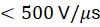 with output filter integration |
| Typical Energy Savings Metric | 30% to 50% reduction in variable torque fluid applications |
Motor Slip Compensation and Vector Control Algorithms
Operating an induction motor via a variable frequency drive requires precise control over magnetic flux vector orientation to maintain high torque output across wide speed ranges. Simple volts-per-hertz ( ) control maintains a constant voltage-to-frequency ratio, but suffers from speed droop under heavy mechanical loads due to rotor slip.
Advanced industrial VFDs implement sensorless vector control or field-oriented control (FOC) algorithms. These digital signal processor (DSP) calculations decouple stator current into independent magnetizing (flux-producing) and torque-producing vector components. By monitoring rotor slip frequency in real time, the VFD adjusts output voltage dynamically, ensuring rapid transient response, full rated torque at zero speed, and precise speed regulation within  of nominal velocity without requiring physical shaft encoders.
The Final Take
Mastering industrial variable frequency drive energy efficiency optimizes electrical power conversion and fluid transport mechanics across global manufacturing infrastructure. Citing IEA industrial assessments and electrical engineering literature, modulating motor rotational speed via pulse-width modulation exploits centrifugal affinity laws to slash power consumption by up to 50%. By mitigating harmonic distortion and deploying vector control algorithms, industrial VFDs establish an indispensable foundation for high-efficiency electric motor management.


Comments (0)
Login to leave a comment.
No comments yet. Be the first to share your thoughts!