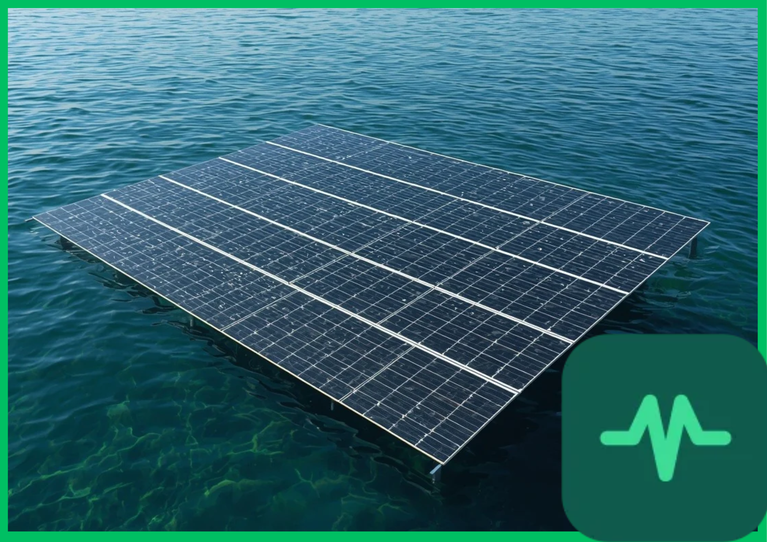
 to
 (
 to
 ), degrading power conversion efficiency due to negative temperature coefficients. Floating photovoltaic systems mitigate this thermal penalty by utilizing natural evaporative cooling and the high thermal capacitance of underlying water bodies, reducing operating module temperatures by
 to
 (
 to
 ) and increasing annual energy yield by 5% to 15% while suppressing reservoir evaporation losses.
Thermal Regulation Physics and Photovoltaic Temperature Coefficients
Semiconductor power output depends directly on operating cell temperature ( ). The maximum power output (
 ) of a silicon photovoltaic module declines linearly as temperature increases above standard test conditions (
 [
 ]), governed by the temperature coefficient of power (
 ). For standard monocrystalline silicon modules,
 ranges from
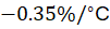 to
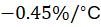 . When land-based modules experience extreme solar noon irradiance, their internal temperatures spike, causing a 15% to 25% drop in nominal power generation capacity compared to rated laboratory output.
Floating photovoltaic systems exploit the continuous convective and evaporative heat transfer of adjacent water bodies. Convective heat loss from the rear surface of the floating racking structure and direct cooling from water vapor transfer maintain module operating temperatures between  and
 (
 to
 ). This thermal suppression preserves open-circuit voltage (
 ) and minimizes power degradation, directly enhancing annual kilowatt-hour yield metrics.
Reservoir Evaporation Reduction and Water Conservation Mechanics
Beyond electrical energy yield improvements, floating photovoltaic systems deliver profound environmental co-benefits through reservoir evaporation reduction. In arid and semi-arid regions, open water reservoirs lose massive volumes of stored water annually due to solar radiation and dry ambient winds driving high evaporation rates.
Shading the water surface with large arrays of floating pontoons blocks direct shortwave solar radiation and dampens wind speed across the water boundary layer. The reduction in net radiative heat flux into the water body suppresses latent heat of vaporization, decreasing annual reservoir evaporation rates by 50% to 90% beneath covered areas. This water conservation metric holds immense strategic value for hydroelectric facility operators and municipal water districts facing severe water stress and declining reservoir levels.
Structural Floating Platforms, Anchoring, and Mooring Engineering
Designing robust floating photovoltaic arrays requires advanced marine engineering and materials science to withstand mechanical stresses induced by wind shear, wave action, and water level fluctuations. Floating platforms are constructed from high-density polyethylene (HDPE) pontoons or modular pontoon-metal hybrid frames engineered to resist ultraviolet radiation degradation, chemical oxidation, and biological fouling over 25-year operational lifespans.
HDPE material exhibits high tensile strength, impact resistance, and flexibility to accommodate dynamic wave motion without structural fatigue. Anchoring and mooring systems—comprising tensioned catenary steel cables, concrete anchor blocks, or deadweight anchors fixed to the reservoir bed—secure the floating island against high-velocity wind loads (up to  to
 [
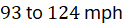 ]) while accommodating vertical water level changes exceeding
 to
 (
 ) in hydroelectric reservoirs.
Technical Data Specifications of Floating Photovoltaic Parameters
| FPV & Thermodynamic Parameter | Engineering Specification Standard |
|---|---|
| Operating Module Temperature Reduction |  to  (  to  ) cooler than land arrays |
| Annual Energy Yield Enhancement | 5% to 15% increase in kilowatt-hour generation |
| Reservoir Evaporation Suppression Rate | 50% to 90% reduction beneath covered water area |
| Pontoon Structural Material Composition | High-Density Polyethylene (HDPE) with UV stabilizers |
| Wind Load Survivability Threshold |  to  ( 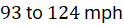 ) wind speed |
| Mooring Line Tension Tolerance | Catenary steel cables designed for dynamic water fluctuation |
| Electrical Ingress Protection Rating | IP67 or IP68 waterproof junction and inverter enclosures |
Grid Integration, Electrical Balance of System, and Environmental Impacts
Integrating floating photovoltaic arrays with electrical grids introduces unique engineering requirements for balance of system (BOS) components. Because electrical equipment operates in humid, corrosive aquatic environments, all inverters, combiner boxes, and cabling must comply with strict ingress protection standards (IP67 or IP68 waterproof ratings).
High-voltage DC cables running from floating arrays to shore-based substations must be suspended on specialized floating cable trays or anchored securely along the reservoir floor using armored, water-resistant subsea cabling. Furthermore, environmental impact assessments published by international agencies confirm that partial reservoir coverage (10% to 30% surface area) prevents excessive light blocking, avoiding adverse disruptions to aquatic flora and fauna while suppressing harmful algal blooms through controlled shade.
The Final Take
Mastering aquatic solar floating photovoltaic evaporative cooling efficiency redefines renewable energy generation by coupling photovoltaic thermal regulation with reservoir water conservation. Citing IEA renewable energy assessments and academic literature, floating solar installations mitigate temperature-induced efficiency losses and suppress open-water evaporation by up to 90%. By integrating high-density polyethylene structural platforms with advanced mooring engineering, floating photovoltaic systems establish an indispensable technical foundation for sustainable water-energy nexus infrastructure.


Comments (0)
Login to leave a comment.
No comments yet. Be the first to share your thoughts!